Sub-module layering voltage-sharing method of modularized multi-level current converter

A modular multi-level, sub-module technology, applied in the direction of converting AC power input to DC power output, electrical components, output power conversion devices, etc. Influence and other issues, to reduce the loss and the risk of equipment failure, improve the dynamic response characteristics, reduce the effect of switching frequency

Active Publication Date: 2014-06-25
ZHEJIANG UNIV
View PDF5 Cites 17 Cited by
  • Summary
  • Abstract
  • Description
  • Claims
  • Application Information

AI Technical Summary

Problems solved by technology

The disadvantages of this method are: 1) The number of sub-modules that need to be sorted in each control cycle is large, and the number of sub-modules whose switching status changes in the end is much smaller than the number of sub-modules that participate in the sorting, which poses a problem for system computing resources. Larger waste will lead to serious control delay and affect the overall stability of the system; 2) The influence of the phase voltage change rate on the sorting operation is not considered, and the phase voltage change rate is approximately proportional to the change in the number of sub-module switching. When the voltage changes are not severe, the traditional method still maintains more sub-modules to be sorted according to the standard of severe voltage changes. This method has too high a sorting margin and increases the computational burden of the system.
Although this method improves the sorting speed of the capacitor voltage of the sub-modules, it still needs to sort all the sub-modules, and does not overcome the disadvantage of large amount of calculation

Method used


Image

  • Sub-module layering voltage-sharing method of modularized multi-level current converter
  • Sub-module layering voltage-sharing method of modularized multi-level current converter
  • Sub-module layering voltage-sharing method of modularized multi-level current converter

Examples


Embodiment Construction

[0032] In order to describe the present invention more specifically, the technical solutions of the present invention will be described in detail below in conjunction with the accompanying drawings and specific embodiments.

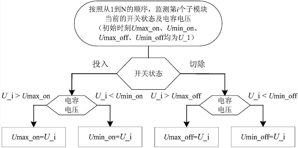
[0033] A sub-module layered voltage equalization method for a modular multilevel converter, the specific steps comprising:

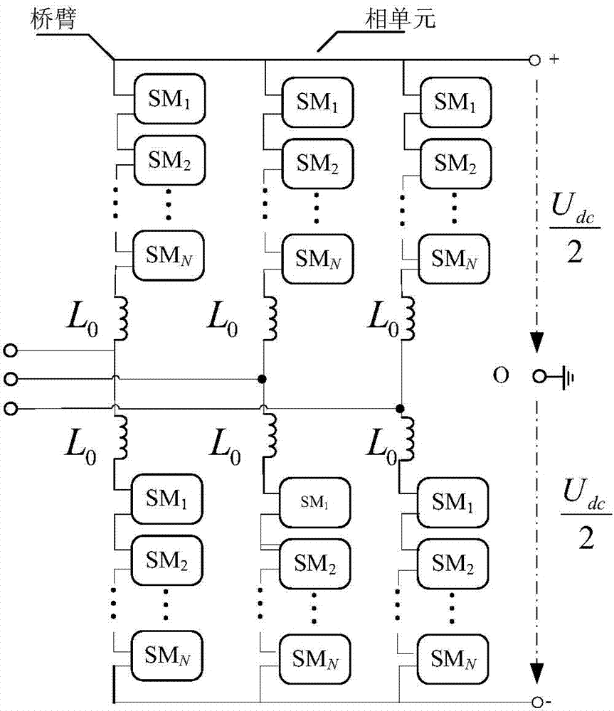
[0034] Step 1: For each bridge arm, monitor the initial switching state of the bridge arm sub-module, record the maximum and minimum values ​​of the capacitor voltage, and monitor the phase θ of the AC voltage of this phase j .

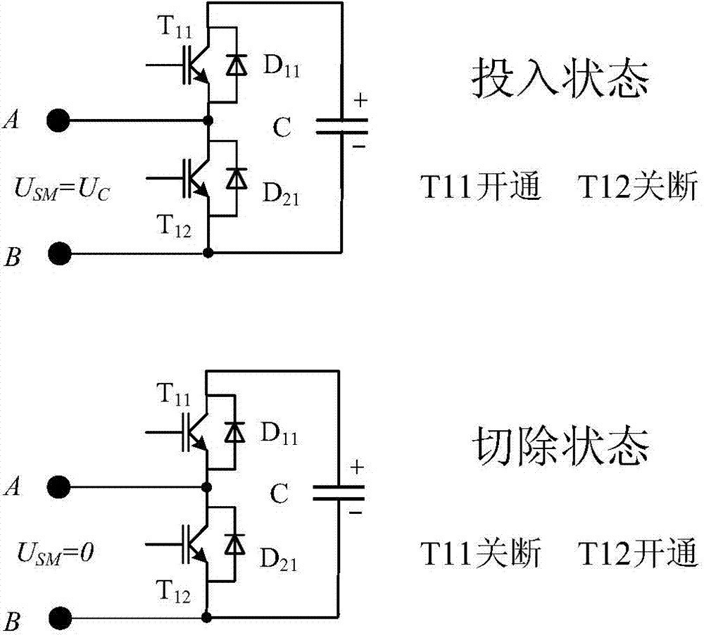
[0035] The MMC topology adopts a three-phase six-leg structure such as figure 1 As shown, each bridge arm is formed by cascading N basic operating power units, and a snubber reactance L is configured at the same time 0 To suppress the rate of rise of circulating current and fault current. udc is the MMC bipolar DC bus voltage difference. Sub-modules in existing projects generally adopt a half-bridge str...


PUM


Abstract

The invention discloses a sub-module layering voltage-sharing method of a modularized multi-level current converter. By monitoring the phase of each phase alternating current voltage, the initial on-off state of each bridge arm sub-module, and the maximum value and the minimum value of capacitor voltage, the sub-modules are layered according to a given layering scale factor gamma and a ranking margin factor eta; the sub-modules located at a corresponding layer are ranked and switched according to the current direction of a bridge arm, the switching change of each sub-module, the phase voltage change rate and other comprehensive factors. The sub-module layering voltage-sharing method of the modularized multi-level current converter provides the two creative control indictors, namely the layering scale factor gamma and the ranking margin factor eta, carries out layering processing on the sub-modules from two control dimensions, only carries out ranking processing on the sub-modules at the corresponding layer every time the electric level changes, shortens the time needed by ranking, keeps the current on-off state of the sub-modules as much as possible at the same time, keeps the on-off frequency at a lower level, improves the response speed of a system, and has high engineering application value.

Description

technical field [0001] The invention belongs to the technical field of power electronics, and in particular relates to a sub-module layered voltage equalization method of a modular multilevel converter. Background technique [0002] In recent years, high-voltage direct current transmission (MMC-HVDC) technology based on MMC (modular multilevel converter, modular multilevel converter) has received extensive attention. The bridge arm of this type of topology adopts the form of cascading basic operating units, avoiding the direct series connection of a large number of switching devices, and there is no problem such as consistent triggering, which greatly reduces the technical barriers of DC power transmission. However, because this topology disperses and stores energy in the capacitors of each sub-module of the bridge arm, how to quickly realize the balanced control of the capacitor voltage of each sub-module during operation is one of the difficulties in its implementation. ...

Claims


Application Information

Patent Timeline
Patent Type & Authority Applications(China)
IPC IPC(8): H02M7/219
Inventor 徐政刘高任许烽
Owner ZHEJIANG UNIV
Why Eureka
Try Eureka