Friction clutch with path-controlled wear compensation
What is Al technical title?
Al technical title is built by PatSnap Al team. It summarizes the technical point description of the patent document.
A friction clutch, path technology, applied in the direction of friction clutch, clutch, mechanical drive clutch, etc., can solve the problem of inaccurate precision and so on
Inactive Publication Date: 2016-05-18
SCHAEFFLER TECH AG & CO KG
View PDF5 Cites 2 Cited by
Summary
Abstract
Description
Claims
Application Information
AI Technical Summary
This helps you quickly interpret patents by identifying the three key elements:
Problems solved by technology
Method used
Benefits of technology
Problems solved by technology
In this way, a substantially constant positioning angle of the lever system, for example a lever spring or a disc spring, relative to the housing can be achieved by means of a constant actuating force of the friction clutch, which is associated with the positioning angle, during the service life of the friction clutch, However, as the service life of the friction clutch increases, the accuracy of wear readjustment may become inaccurate
Method used
Image
Click on the blue label to locate the original text in one second.
Reading with bidirectional positioning of images and text.
Examples
Embodiment Construction
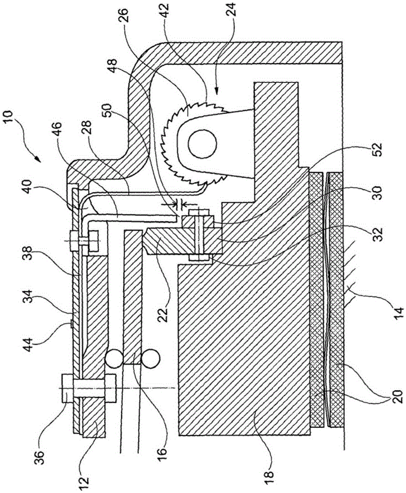
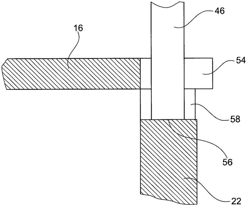
[0024] According to the prior art, for example, it can be arranged in the drive train in the figure 1 The friction clutch 10 shown in has a housing 12 and a counter pressure disc 14 which is fixedly received on said housing, only schematically indicated, displaceable axially by a lever system 16 such as a disk spring, and A pressure plate 18 , which is connected in a rotationally fixed manner to the housing 12 , can be clamped against the counter pressure plate so that it forms a friction fit with the friction lining 12 of the output disk (not shown). In order to compensate for axial wear of the friction lining 20 , an adjusting ring 22 is arranged between the lever system 16 and the pressure plate 18 , which is rotated by the spindle drive 24 when wear is detected. For this purpose, when a prolonged path of the pressure plate 18 relative to the housing 12 is obtained due to wear, in the worn state, the ratchet 26 connected to the main shaft of the spindle drive 24 and the dri...
PUM
Abstract
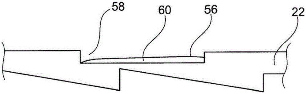
A friction clutch (10) having a housing (12) with a pressure plate (18) which is arranged in a rotationally conjoint manner and so as to be axially displaceable to a limited extent relative to said housing, which pressure plate can, by a lever system (16) supported on the housing, be displaced axially relative to a counterpressure plate, arranged fixedly with respect to the housing, so as to exert a bracing action on friction linings of a clutch disc, wherein in the event of a spacing, formed when the friction linings are braced, between the pressure plate and counterpressure plate being undershot, positive locking is generated between a pinion (26), said pinion being connected to a spindle of a spindle drive (24) which is arranged on the pressure plate and which serves for the rotational drive of an adjusting ring (22) arranged between the pressure plate and the lever system, and a drive pawl (28) fastened to the housing elastically under preload in the direction of the pressure plate, and said positive locking is eliminated during an actuating movement of the pressure plate relative to the housing after a rotation of the pinion by means of the drive pawl, wherein an axial travel of the drive pawl relative to the pinion is delimited by means of the adjusting ring with a contact surface and with a spacer arranged on the housing, wherein the spacer can make contact with the contact surface over a substantially axial adjustment travel of the adjusting ring, characterized in that the spacer runs through a cutout, formed as a passage, of the lever system to a point of abutment against the contact surface, wherein the contact surface is formed as a base of a cutout which is arranged in a surface, arranged opposite the pressure plate, of the adjusting ring and which is in the form of a base depression. In this way, it is possible to permit an improvement in the accuracy of the wear readjustment and, in so doing, to minimize the required installation space.
Description
technical field [0001] The invention relates to a friction clutch with path-controlled wear compensation. Background technique [0002] Such a friction clutch is known, for example, from DE 10 2008 051 100 A1. Wear compensation of the friction linings in such friction clutches for the wear that occurs during the service life of the friction clutch is brought about by the arrangement of an adjusting ring between the pressure plate and the lever system acting on the pressure plate, wherein the The adjusting ring has a slope arranged in the circumferential direction, which, together with the matching slope arranged on the pressure plate, compensates for the friction between the mating pressure plate and the pressure plate caused by the axially worn friction lining when the adjusting ring is rotated. space, and thus a reduced distance between the mating pressure plate and the lever system. In this way, a substantially constant positioning angle of the lever system, for example...
Claims
Application Information
Patent Timeline
Application Date:The date an application was filed.
Publication Date:The date a patent or application was officially published.
First Publication Date:The earliest publication date of a patent with the same application number.
Issue Date:Publication date of the patent grant document.
PCT Entry Date:The Entry date of PCT National Phase.
Estimated Expiry Date:The statutory expiry date of a patent right according to the Patent Law, and it is the longest term of protection that the patent right can achieve without the termination of the patent right due to other reasons(Term extension factor has been taken into account ).
Invalid Date:Actual expiry date is based on effective date or publication date of legal transaction data of invalid patent.
