Vacuum cleaning chamber

A technology for vacuum cleaning and cleaning chambers, applied in cleaning methods and utensils, cleaning methods using liquids, chemical instruments and methods, etc., can solve the problems of soft spots, difficulty in cleaning furnaces, deterioration of workshop environment, etc., to ensure the cleaning effect. , The effect of improving cleaning efficiency and good thermal insulation performance

Inactive Publication Date: 2014-07-02
HEPHAES HEAT TREATMENT SYST JIANGSU
View PDF10 Cites 5 Cited by
  • Summary
  • Abstract
  • Description
  • Claims
  • Application Information

AI Technical Summary

Problems solved by technology

[0002] There will always be a certain amount of oil stains on the surface of mechanical parts. If the cleaning is not clean, the residual oil stains will pollute the vacuum furnace during heat treatment in the vacuum furnace, affecting the quality of heat treatment, and it is also difficult to clean the furnace; for general atmosphere furnaces, after quenching If the cleaning is not clean, a large amount of smoke will be produced during tempering, which will shorten the service life of the tempering furnace on the one hand, and worsen the workshop environment on the other hand
[0003] Most of the traditional cleaning methods use to soak the parts to be cleaned in the cleaning solution, and then spray them with clean water. This method is not only difficult to clean the holes, grooves and grooves of some complicated parts, but also the whole process is manually operated. The working environment is harsh, and the cleaning effect is not good. After heat treatment, the surface color of the workpiece is not good, and there will be soft spots in the uncleaned parts such as nitriding / carburizing, which seriously affects the quality of heat treatment; Bring it into the tempering furnace, and there will be a danger of explosion in severe cases

Method used


Image

  • Vacuum cleaning chamber
  • Vacuum cleaning chamber

Examples


Embodiment 1)

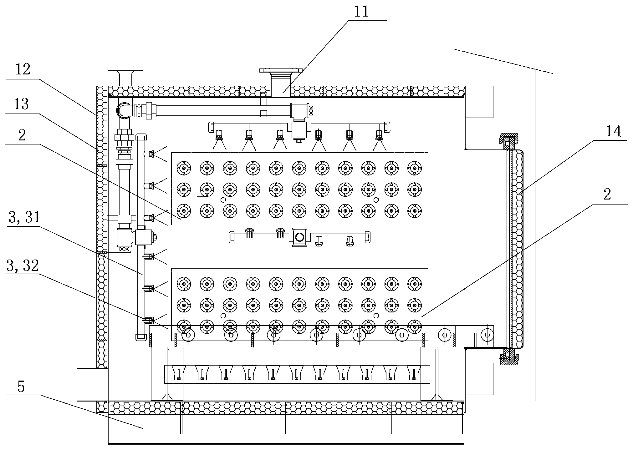
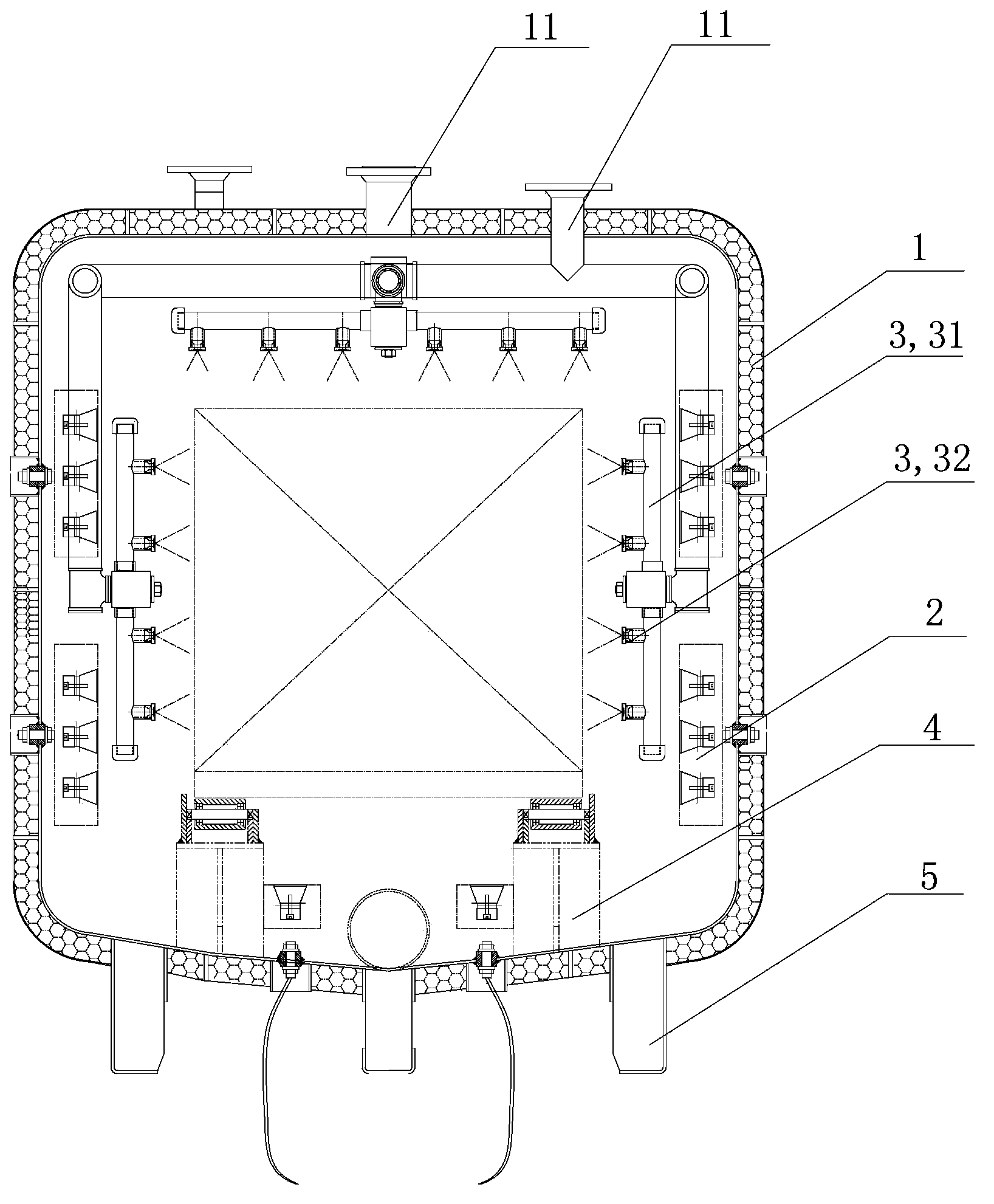
[0021] See figure 1 and figure 2 , the present invention has a cleaning chamber housing 1 with a furnace door 14 on one side, a plurality of through holes 11 are provided at the upper end of the cleaning chamber housing, and the vacuum piping system and the cleaning piping system can pass through the through holes 11 to enter the inside of the cleaning chamber. An ultrasonic vibrating plate 2 is arranged on the inner wall of the cleaning chamber shell 1, and the ultrasonic vibrating plate 2 is connected with an external ultrasonic controller.

[0022] Preferably, a spray device 3 is also provided on the outside of the cleaning chamber wall, and the spray device 3 includes a water spray pipe 31 and several spray ports 32 uniformly distributed on the top of the water spray pipe 31; The water pump is connected.

[0023] Preferably, the inner bottom surface of the vacuum cleaning chamber housing 1 is provided with a workpiece fixing bracket 4 for fixing the workpiece so that th...


PUM


Abstract

The invention relates to cleaning equipment for heat treatment, in particular to a vacuum cleaning chamber for heat treatment. The vacuum cleaning chamber comprises a cleaning chamber shell. A furnace door is arranged on a side of the cleaning chamber shell, a plurality of through holes are formed in the upper end of the cleaning chamber shell, and ultrasonic vibrating plates are arranged on the inner wall of the cleaning chamber shell and are connected with an external ultrasonic controller. The vacuum cleaning chamber has the advantages that heat treatment workpieces can be conveniently and automatically cleaned in a closed vacuum system, the vacuum cleaning chamber is high in cleaning degree, and accordingly the cleaning efficiency can be greatly improved; the ultrasonic vibrating plates are arranged in the cleaning chamber for assisting in cleaning the workpieces, so that stubborn dirt on the surfaces of the workpieces can be quickly removed, cleaning dead zones of complicated workpieces with holes, grooves and the like can be effectively cleaned, and the quantities of residual oil on the surfaces of the workpieces can be greatly reduced.

Description

technical field [0001] The invention relates to a cleaning device for heat treatment, in particular to a vacuum cleaning chamber for heat treatment. Background technique [0002] There will always be a certain amount of oil stains on the surface of mechanical parts. If the cleaning is not clean, the residual oil stains will pollute the vacuum furnace during heat treatment in the vacuum furnace, affecting the quality of heat treatment, and it is also difficult to clean the furnace; for general atmosphere furnaces, after quenching If the cleaning is not clean, a large amount of smoke will be produced during tempering, which will shorten the service life of the tempering furnace on the one hand, and worsen the workshop environment on the other hand. [0003] Most of the traditional cleaning methods use to soak the parts to be cleaned in the cleaning solution, and then spray them with clean water. This method is not only difficult to clean the holes, grooves and grooves of some ...

Claims


Application Information

Patent Timeline
Patent Type & Authority Applications(China)
IPC IPC(8): B08B3/12B08B3/02
CPCB08B3/12B08B3/02
Inventor 陈德义张牛山朱景华
Owner HEPHAES HEAT TREATMENT SYST JIANGSU
Why Eureka
Try Eureka