Three-dimensional printing large light spot scanning path generation method

A scanning path and 3D printing technology, which is applied in the field of efficient scanning path generation with large light spots in 3D printing

Active Publication Date: 2014-07-02
ZHEJIANG UNIV
View PDF3 Cites 54 Cited by
  • Summary
  • Abstract
  • Description
  • Claims
  • Application Information

AI Technical Summary

Problems solved by technology

Aiming at the problem of unscanned areas that may be generated when the large spot is offset, first use the Boolean operation of the planar area to find these unscanned areas, and then generate parallel scanning paths with smaller spots in these areas

Method used


Image

  • Three-dimensional printing large light spot scanning path generation method
  • Three-dimensional printing large light spot scanning path generation method
  • Three-dimensional printing large light spot scanning path generation method

Examples


Embodiment

[0067] A typical implementation example of the present invention is as follows:

[0068] 1. The part to be printed selected in this example is a puppy STL model, such as Figure 6 shown. The size of the model is about 350mm×350mm×12mm, of which 12mm is the height of the model.

[0069] 2. the puppy STL model is imported into commercial software Magics RP to generate slice files, then the slice files are imported in the test program written by the method of the present invention with C++ language.

[0070] 2. In the test program, the three-dimensional printing process is selected as photocuring, the maximum spot diameter is set to 4mm, and the minimum spot diameter is set to 0.1mm, that is, r max =2mm, r min =0.05mm; path overlap parameter f=1, that is, two adjacent paths do not overlap each other.

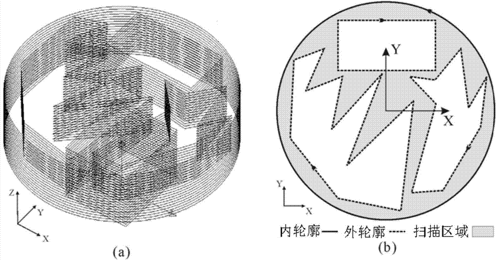
[0071] Figure 7 The scan path generated for one slice of the puppy model slice file is given. This layer slice contains a total of 9 contour curves, one of which is the oute...


PUM


Abstract

The invention discloses a three-dimensional printing large light spot scanning path generation method which comprises the steps of inputting a model slice file, the maximum light spot radius rmax, the minimum light spot radius rmin and a path overlapping parameter f; performing offset on a contour boundary bi of the current layer of the slice for the rmin to generate a small light spot contour scanning path ps, and performing offset on the ps for the rmin to obtain an internal boundary bs of small light spots subjected to scanning; performing offset on the bs for the rmax to obtain a large light spot contour scanning path pb, and performing offset on the pb for the rmax to obtain an internal boundary bb of large light spots subjected to scanning; performing offset on the pb for -rmax to obtain an internal boundary bg of the large light spots subjected to scanning, and performing Boolean subtraction on bs and bg; generating a small light pot parallel scanning path in an unscanned region; connecting all the large light pot scanning paths and all the small light pot scanning paths until printing is completed and the scanning paths are output. By means of the three-dimensional printing large light spot scanning path generation method, the small light spot scanning and the large light spot scanning are combined, the unscanned region is filled with the small light spots to achieve elimination, and part forming accuracy and efficiency are increased.

Description

technical field [0001] The invention relates to the field of three-dimensional printing CAM path planning, in particular to a method for generating a large-spot high-efficiency scanning path for three-dimensional printing. Background technique [0002] 3D printing technology is a cutting-edge technology developed on the basis of information technology and material science. It originated from the photosculpture and landform shaping technology at the end of the 19th century, and was developed and promoted in the 1980s. Since its birth, 3D printing has been defined as a revolutionary technology that subverts traditional production methods. It has become a key word leading the development trend of global manufacturing in the future. It is the greatest invention after the steam engine, electricity, and the Internet. The US "Time" magazine has listed the 3D printing industry as "the ten fastest-growing industries in the United States", and the British "Economist" magazine even li...

Claims


Application Information

Patent Timeline
Patent Type & Authority Applications(China)
IPC IPC(8): B22F3/105B22F3/115B29C67/00
Inventor 傅建中林志伟赖金涛付国强贺永沈洪垚
Owner ZHEJIANG UNIV
Why Eureka
Try Eureka