A special cutting tool for helical milling holes of laminated materials

A technology of helical hole milling and lamination of materials, applied in milling cutters, manufacturing tools, milling machine equipment, etc., can solve the problem of optimal design without cutting edge layout, reduce delamination and burrs, suppress vibration, and improve hole exit quality. Effect

Active Publication Date: 2016-02-10
ZHEJIANG UNIV
View PDF12 Cites 0 Cited by
  • Summary
  • Abstract
  • Description
  • Claims
  • Application Information

AI Technical Summary

Problems solved by technology

The patent focuses on the influence of the position and layout of the cooling holes on chip removal, and does not optimize the design of the cutting edge layout of the end edge and side edge

Method used


Image

  • A special cutting tool for helical milling holes of laminated materials
  • A special cutting tool for helical milling holes of laminated materials
  • A special cutting tool for helical milling holes of laminated materials

Examples


Embodiment Construction

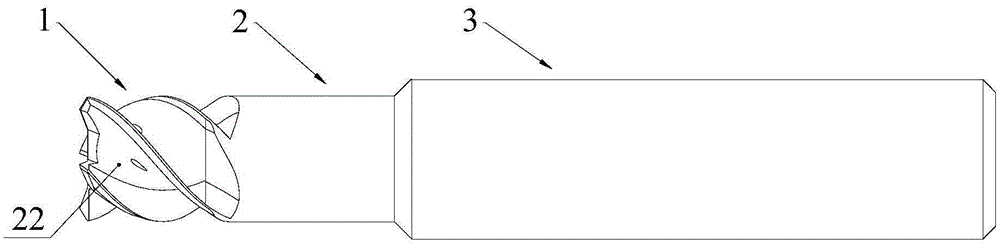
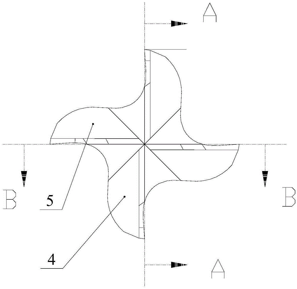
[0031] Such as Figure 1~2 As shown, a special cutting tool for helical milling of laminated materials includes a cutting head 1, a neck 2 and a tool bar 3 connected in sequence. The axially symmetrical cutter teeth of the cutter bar are the first cutter teeth 4, the other pair of cutter teeth are the second cutter teeth 5, and the neck side wall is provided with four side edges connected with the corresponding cutter teeth.

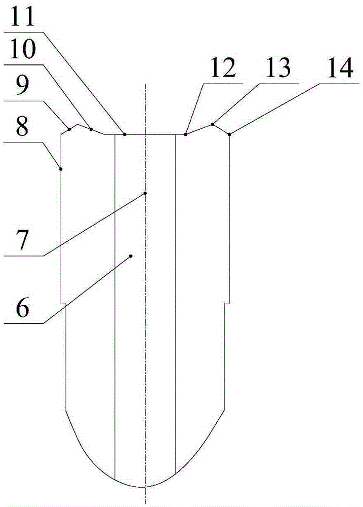
[0032] Such as image 3 As shown, the first cutter tooth 4 includes a first inner cutting edge 11, a first middle cutting edge 10, and a first outer cutting edge 9 connected in sequence, the first inner cutting edge is perpendicular to the axis 7 of the cutter bar, and The cutting edge intersects at the first cutting edge inflection point 12, the first middle cutting edge intersects the first outer cutting edge at the first middle tool point 13, and the first outer cutting edge intersects the corresponding first side edge 8 at the first outer The tool ...


PUM


Abstract

The invention discloses a special tool for helically milling a hole in a laminated material. The tool comprises a cutting head, a neck and a tool bar which are connected in sequence, wherein four tool teeth are arranged at the end of the cutting head, and four side edges are arranged at the neck; two of the four tool teeth are first tool teeth, and the other two of the four tool teeth are second tool teeth; each tool tooth comprises an inner cutting edge, a middle cutting edge and an outer cutting edge which are connected in sequence; all the inner cutting edges are positioned in the same plane; the first tool teeth and the second tool teeth form a distributed multi-lattice layout structure. According to the tool, the distributed multi-lattice layout design is realized by virtue of the first tool teeth and the second tool teeth; an interface of the laminated material with large physical property difference can be cut efficiently and stably at a variable speed due to the structure; meanwhile, the cutting proportion of the side edges is reduced, the holing quality is ensured, and the overall life of the tool is further prolonged.

Description

technical field [0001] The invention relates to a special tool for helical milling holes, in particular to a special tool for helical milling holes of laminated materials. Background technique [0002] With the rapid development of the aviation industry, in order to effectively improve the structural strength of the aircraft, reduce the weight of the aircraft structure, and reduce the energy consumption of the aircraft, a large number of laminated structures composed of aluminum alloys, titanium alloys, and carbon fiber composite materials (CFRP) are used on aircraft. This kind of laminated structure is widely used especially in aircraft wings. The wing panels are made of composite materials, and the skeleton is made of aluminum and titanium alloys. The traditional drilling technology can no longer meet the product requirements. For titanium alloys, the traditional drilling technology is difficult to solve technical problems such as exit burrs and surface smoothness; for co...

Claims


Application Information

Patent Timeline
Patent Type & Authority Patents(China)
IPC IPC(8): B23C5/10
Inventor 刘刚周兰柯映林
Owner ZHEJIANG UNIV
Why Eureka
Try Eureka