Energy-saving dyeing machine

A dyeing machine and dyeing liquor technology, which is applied in the direction of liquid/gas/steam jet propulsion of fabrics, equipment configuration for processing textile materials, etc., can solve the problems of high energy consumption, waste, and high production costs in wastewater treatment, and achieve the reduction of wastewater discharge, Reduced production costs and reduced usage

Inactive Publication Date: 2014-07-02
NINGBO EASTSUN TEXTILES
View PDF7 Cites 3 Cited by
  • Summary
  • Abstract
  • Description
  • Claims
  • Application Information

AI Technical Summary

Problems solved by technology

In order to drive the fabric to circulate in the master vat, the fabric must be continuously impacted with the dye solution. Therefore, the bath ratio must be increased. However, the increase of the bath ratio will cause a long heating time and a long cooling time of the dye solution, which is very wasteful. Resources such as steam, water, and electricity
At the same time, too much water is consumed in the dyeing process, the energy consumption of wastewater treatment is too large, the utilization rate of dyestuff is low, the dyeing time is long, the production efficiency is low, and the production cost is high, which cannot meet the needs of energy saving, emission reduction, low-carbon environmental protection.

Method used


Image

  • Energy-saving dyeing machine
  • Energy-saving dyeing machine
  • Energy-saving dyeing machine

Examples


Embodiment Construction

[0014] The present invention will be further described in detail below in conjunction with the accompanying drawings and specific embodiments.

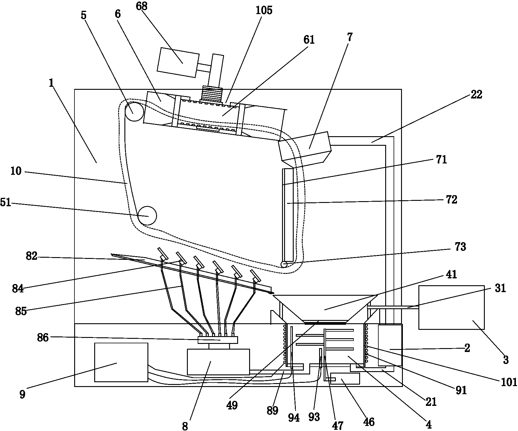
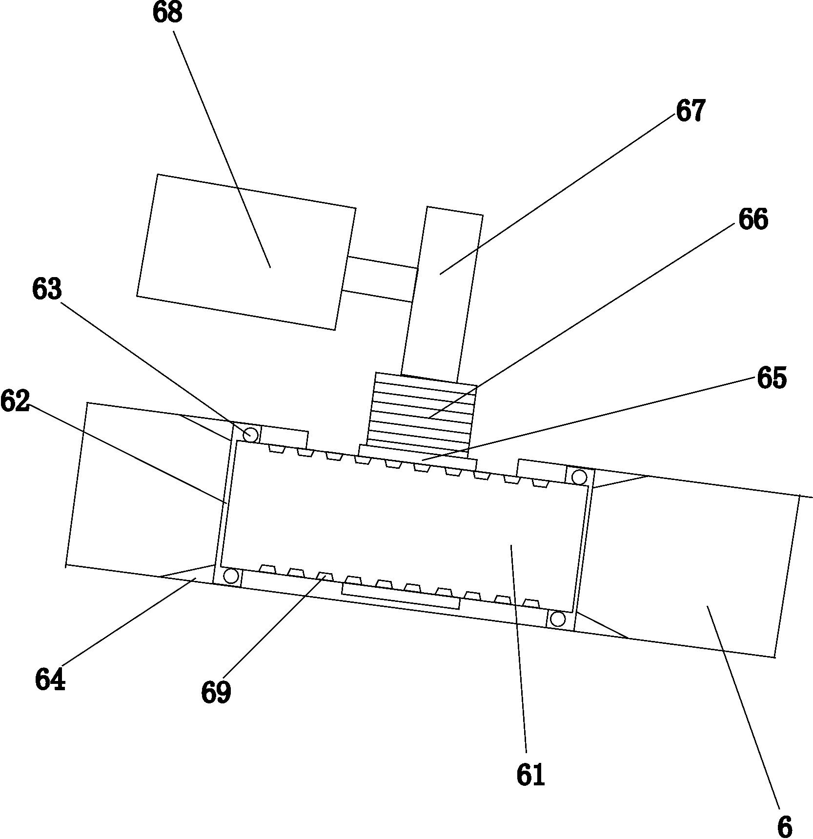
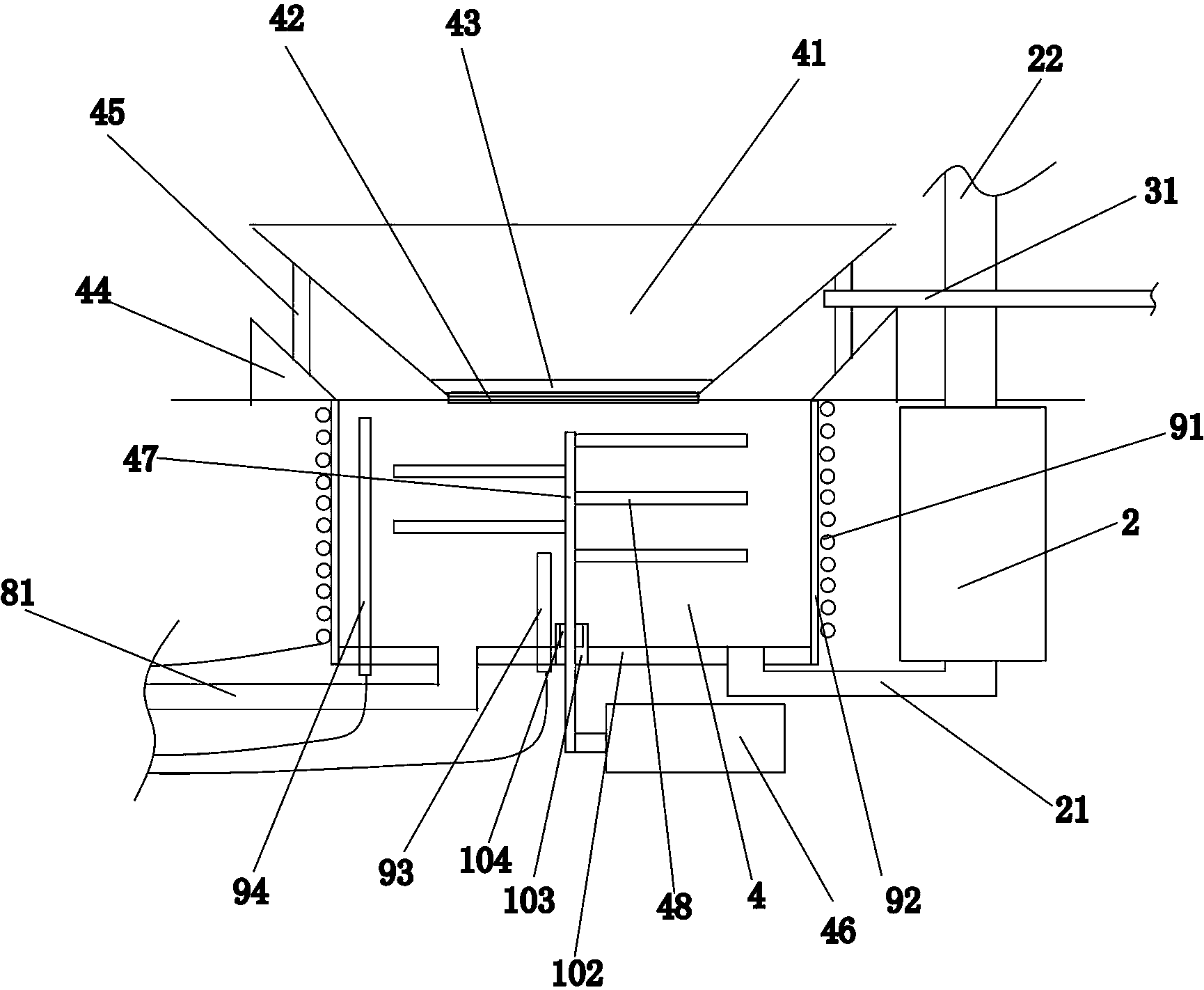
[0015] Such as figure 1 , figure 2 , image 3 and Figure 4 As shown, a dyeing machine includes a cylinder body 1, a circulation pump 2, and a dye solution tank 3. A cloth lifting wheel 5, a cloth guide pipe 6, and a large nozzle 7 are arranged in the cylinder body 1. The bottom of the cylinder body 1 is provided with a groove 4, the groove 4 is located directly below the large nozzle 7, the groove 4 includes a circular iron side wall 101 and a bottom plate 102 made of ceramic material, and the side wall 101 is wrapped with an insulating material 92. The thermal insulation material 92 can be thermal insulation cotton, or other thermal insulation materials. An electromagnetic coil 91 is arranged around the insulating material 92 , and the electromagnetic coil 91 surrounds and wraps the side wall 101 . The bottom of the groove 4 i...


PUM


Abstract

The invention discloses an energy-saving dyeing machine and relates to an electromagnetic heating dyeing machine. The energy-saving dyeing machine comprises a cylinder body, a circulation pump and a dyeing liquid box. A large nozzle, a cloth guiding pipe and a cloth lifting wheel are arranged in the cylinder body. A groove is formed in the bottom of the cylinder body and formed under the large nozzle. The groove comprises a round iron side wall and a base plate which is made of ceramic materials. The side wall is wrapped by heat preservation materials, and an electromagnetic coil is arranged on the heat preservation materials in a surrounding mode. The electromagnetic coil is connected with a heating controller, and the bottom of the groove is provided with a first dyeing liquid pipe connected with the circulation pump. The circulation pump is provided with a second dyeing liquid pipe connected with the large nozzle, and the dyeing liquid box is provided with a conveying pipe matched with the groove. Compared with the prior art, an electromagnetic heating manner is used for replacing a previous heat exchanger heating manner, the user amount of water and electricity can be greatly reduced, energy is greatly saved, production cost is reduced, and meanwhile due to the fact that the use amount of water is reduced, and discharging amount of waste water is reduced.

Description

technical field [0001] The invention belongs to a kind of dyeing equipment, in particular to an electromagnetic heating dyeing machine. Background technique [0002] The dyeing machine has many uses, for example, it can be mainly used for dyeing, bleaching, scouring and washing of woolen sweaters, acrylic and cotton sweaters, etc. It can also be used for bleaching and dyeing of gloves, socks, towels and other finished products. A kind of bleaching and dyeing equipment suitable for a wide range. The main working principle of the dyeing machine is to use the circulation pump to promote the circulation of the dye liquor along the pipeline, and the temperature of the dye liquor is raised to 130°C-135°C through the heat exchanger assembly, and then flows through the filter assembly to filter and flow to the nozzle assembly, the nozzle assembly The dyeing liquid is sprayed onto the fabric under the pressure drive, and the fabric is pushed into the cloth guide pipe. The dye liqui...

Claims


Application Information

Patent Timeline
Patent Type & Authority Applications(China)
IPC IPC(8): D06B3/28D06B23/22
Inventor 周秋月
Owner NINGBO EASTSUN TEXTILES
Why Eureka
Try Eureka