
Energy-saving control method, device and system for rotary drilling rig

A rotary drilling rig, energy-saving control technology, applied in the automatic control system of drilling, earthwork drilling, drilling equipment, etc., can solve the problems of no adjustment function, narrow coverage, etc., to reduce pollution emissions, reduce fuel costs, and improve competition. power and economic effects

Active Publication Date: 2014-07-02
XCMG CONSTR MACHINERY
View PDF13 Cites 8 Cited by
  • Summary
  • Abstract
  • Description
  • Claims
  • Application Information

AI Technical Summary

Problems solved by technology

[0007] 1. For the self-adaptive control of the motor load of the power head, the motor is automatically adjusted within a certain pressure range, but the pressure and displacement can only be adjusted according to a single linear rule; outside the pressure range, it is a quantitative motor without adjustment function
[0008] 2. Limit load control: According to the maximum power of the engine at each target speed, set the upper limit of the power of the pump. When the system reaches the upper limit of power, the pump will work at a constant power to match the power of the engine, which can prevent the engine from overloading and stalling. Play a certain role in energy saving, but the coverage is narrow, only suitable for heavy load

Method used


Image

  • Energy-saving control method, device and system for rotary drilling rig
  • Energy-saving control method, device and system for rotary drilling rig
  • Energy-saving control method, device and system for rotary drilling rig

Examples


Embodiment Construction

[0070] The following will clearly and completely describe the technical solutions in the embodiments of the present invention with reference to the accompanying drawings in the embodiments of the present invention. Obviously, the described embodiments are only some, not all, embodiments of the present invention. The following description of at least one exemplary embodiment is merely illustrative in nature and in no way taken as limiting the invention, its application or uses. Based on the embodiments of the present invention, all other embodiments obtained by persons of ordinary skill in the art without creative efforts fall within the protection scope of the present invention.

[0071] The relative arrangements of components and steps, numerical expressions and numerical values ​​set forth in these embodiments do not limit the scope of the present invention unless specifically stated otherwise.

[0072] At the same time, it should be understood that, for the convenience of d...


PUM


Abstract

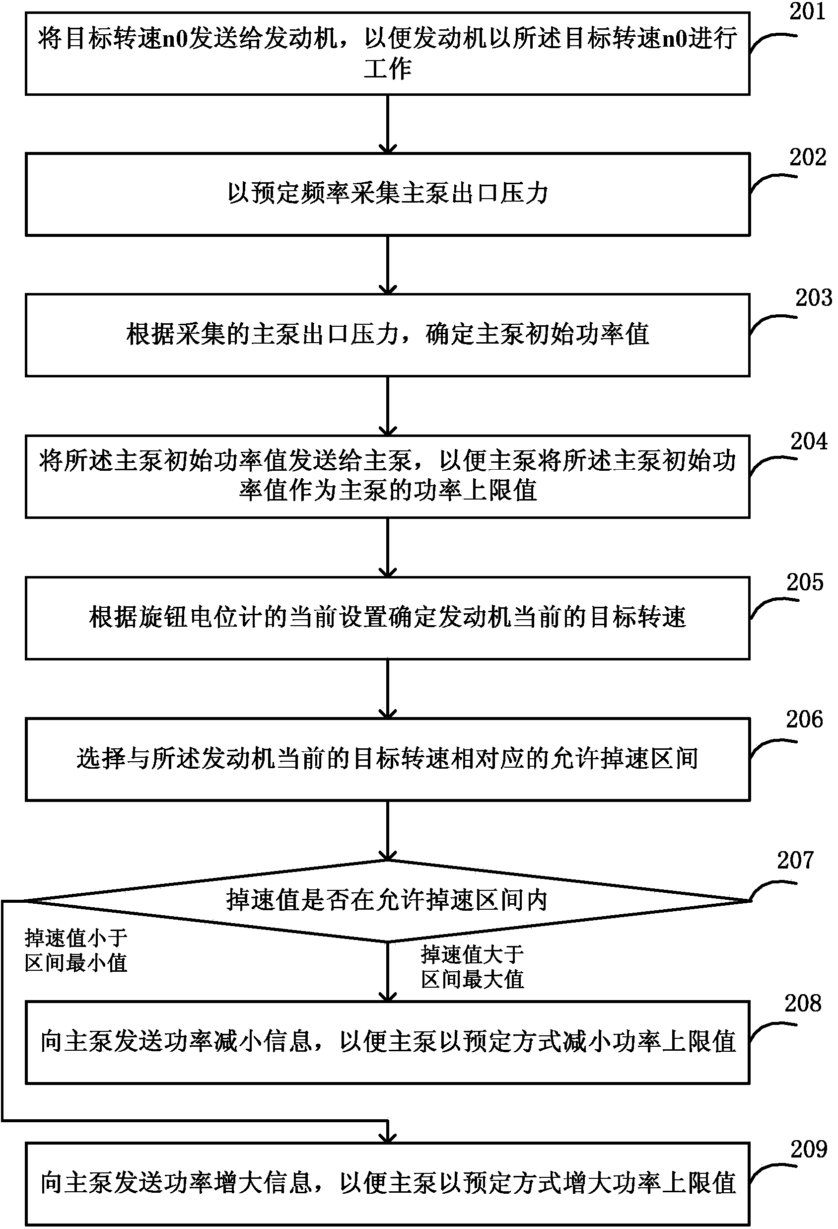
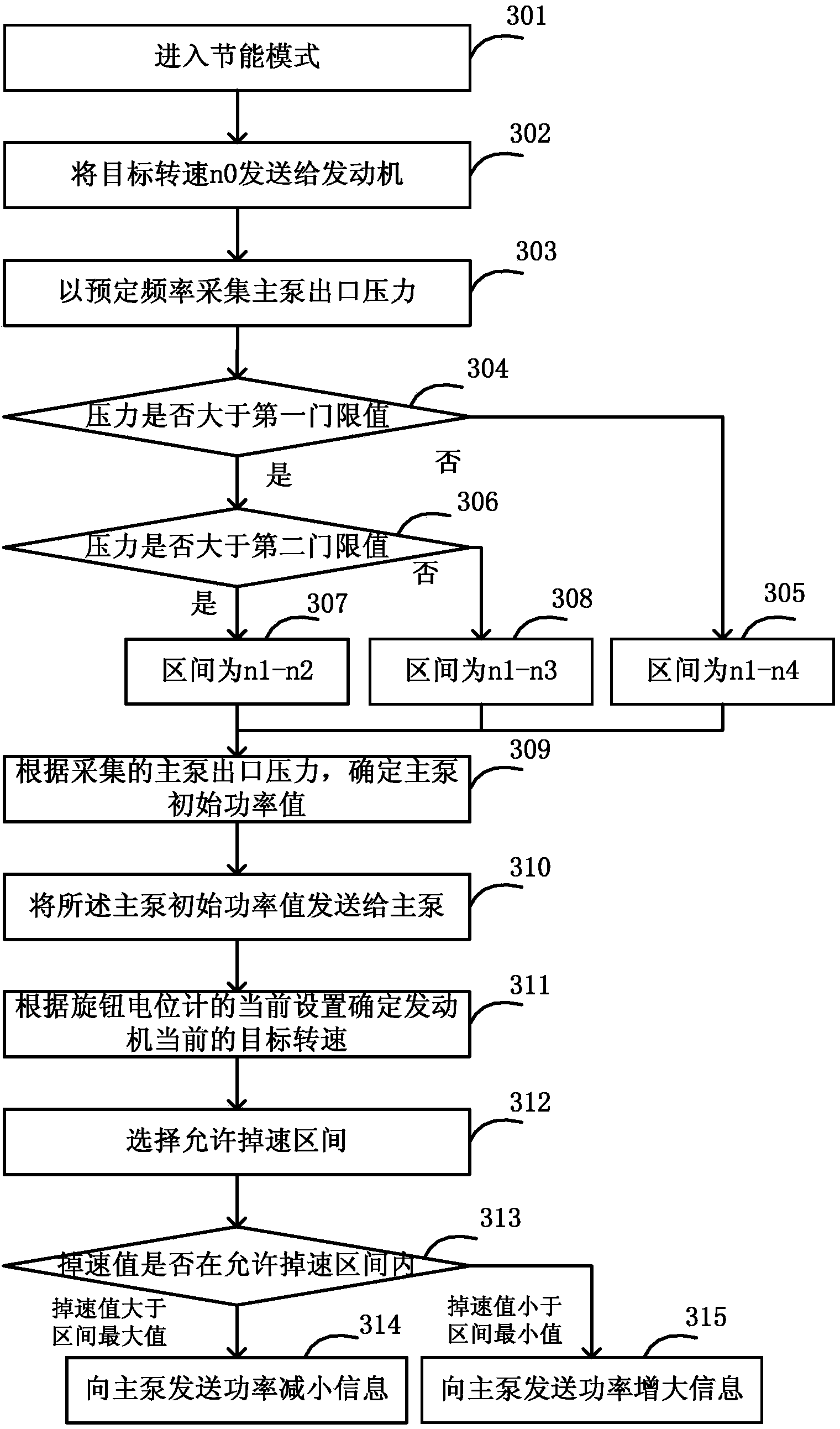
The invention discloses an energy-saving control method, device and system for a rotary drilling rig. In the energy-saving mode, the target rotating speed n0 is sent to an engine so that the engine can work at the n0 target rotating speed; pressure of an outlet of a main pump is collected at preset frequency; according to the collected pressure of the outlet of the main pump, the initial power value of the main pump is determined; the initial power value of the main pump is sent to the main pump so that the initial value of the main pump can be used as the upper limit power value of the main pump; according to the current setting of a knob potentiometer, the current target rotating speed of the engine is determined; a speed adjusting allowed interval corresponding to the current target rotating speed of the engine is selected; whether the speed adjusting value is within the speed adjusting allowed interval or not is judge; if the speed adjusting value is larger than the maximum value of the speed adjusting allowed interval, the main pump is indicated to decrease the upper limit power value; if the speed adjusting value is smaller than the minimum value of the speed adjusting allowed interval, the main pump is indicated to increase the upper limit power value. In this way, energy is effectively saved, the fuel cost is reduced, and competitiveness and economic benefits of manufacturers are improved.

Description

technical field [0001] The invention relates to the field of engineering machinery, in particular to an energy-saving control method, device and system for a rotary drilling rig. Background technique [0002] Rotary drilling rig is a kind of pile construction machinery and equipment, which has been widely used in foundation construction projects such as cast-in-place piles, diaphragm walls, and foundation reinforcement. It is the most ideal construction machine for hole-forming operations. The operating environment of rotary drilling rigs is relatively harsh, and the construction conditions are relatively complicated. According to different geological conditions, such as soil layers and rock layers, the load of the power head is also different. If the output of the power system does not match the load, it will lead to waste of power, or The system is overloaded. [0003] The energy saving of rotary drilling rigs is mainly reflected in the fuel consumption rate. If the fuel ...

Claims


Application Information

Patent Timeline
IPC IPC(8): E21B44/00
Inventor 左帅胡传正徐楠
Owner XCMG CONSTR MACHINERY
Learn More