
Energy-saving pump driven by low-grade heat sources and based on phase change of working media and pump unit

A low-grade heat source, energy-saving pump technology, applied in the direction of pumps, pumps, machines/engines with flexible working elements, etc., can solve the problems of high cost, energy consumption and pollution, and achieve low cost, low pollution, and economical realization. sexual effect

Inactive Publication Date: 2014-07-02
ZHEJIANG UNIV
View PDF5 Cites 1 Cited by
  • Summary
  • Abstract
  • Description
  • Claims
  • Application Information

AI Technical Summary

Problems solved by technology

[0006] Among the existing low-grade heat source utilization technologies, there are organic Rankine cycle combined with steam turbines to generate electricity, and photovoltaic water pumps that use solar panels to directly convert solar energy into electrical energy, but the former is mainly aimed at low-grade heat sources with higher temperatures , the cost of the latter is relatively high, and the energy consumption and pollution are relatively large in the production process

Method used


Image

  • Energy-saving pump driven by low-grade heat sources and based on phase change of working media and pump unit
  • Energy-saving pump driven by low-grade heat sources and based on phase change of working media and pump unit
  • Energy-saving pump driven by low-grade heat sources and based on phase change of working media and pump unit

Examples


Embodiment Construction

[0041] Below in conjunction with each accompanying drawing, the present invention is described in detail.

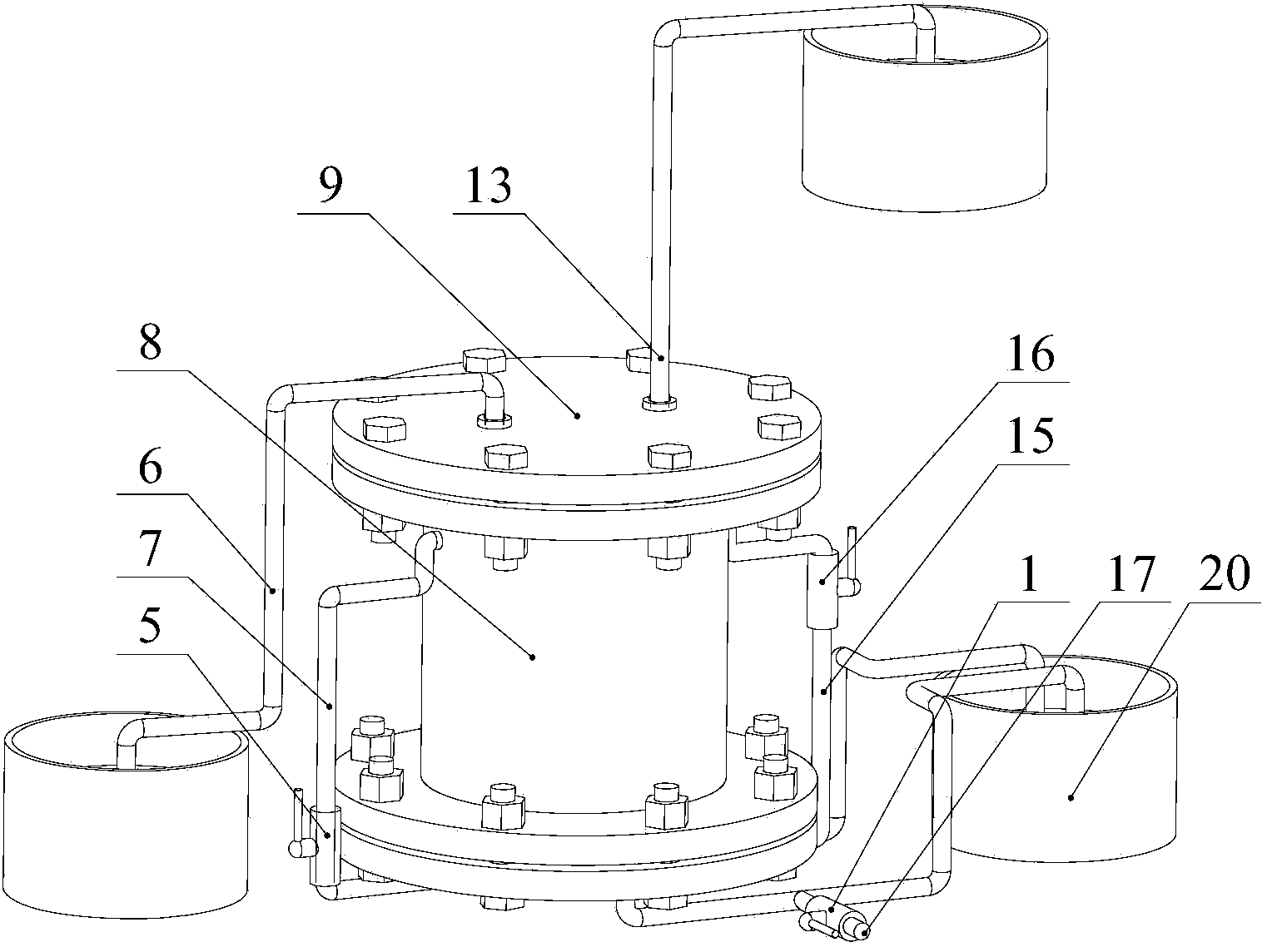
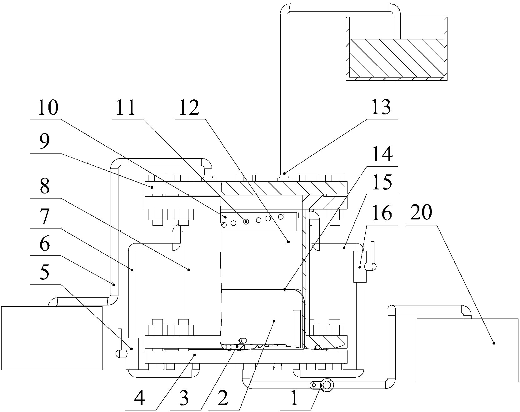
[0042] Such as figure 1 , 2 As shown, a low-grade heat source-driven energy-saving pump based on the phase change of working fluid, including:

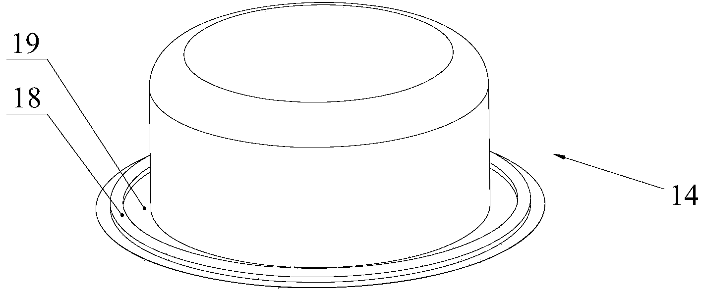
[0043]The pump casing is composed of a cylindrical casing 8 and an upper flange cover 9 and a lower flange cover 4 that are sealed at both ends of the casing; it is located in the casing 8 and divides the internal space of the pump casing into a power chamber 2 and an infusion chamber 12 The heat insulation film 14 of two parts; the heating coil 3 located in the power chamber 2 ; the condensation pipe 11 located in the infusion chamber 12 .

[0044] The infusion chamber 12 is respectively connected with a one-way liquid inlet pipe 6 and a one-way liquid outlet pipe 13, and the one-way liquid inlet pipe and the one-way liquid outlet pipe are respectively provided with a one-way valve, and the one-way flow is realized by setting...


PUM


Abstract

The invention discloses an energy-saving pump driven by low-grade heat sources and based on phase change of working media and a pump unit. The energy-saving pump comprises a pump casing, a heat-insulation film, a condensation pipe and a heating coil pipe. The heat-insulation film is positioned in the pump casing, the inside of the pump casing is divided into a power cavity and a liquid delivery cavity by the heat-insulation film, and the liquid delivery cavity is communicated with a one-way liquid inlet pipe and a one-way liquid outlet pipe respectively; the condensation pipe is positioned in the liquid delivery cavity, and an inlet and an outlet of the condensation pipe are communicated with the power cavity via external circulation of the pump; the heating coil pipe is positioned in the power cavity. The pump unit comprises at least two energy-saving pumps. The energy-saving pump and the pump unit have the advantages that the power cavity of the energy-saving pump is expanded and then squeezes the liquid delivery cavity, so that to-be-delivered liquid can flow out of the energy-saving pump, and functions of a water pump can be realized; the area of the heat-insulation film is sufficiently large, so that elastic force can be prevented from being generated in expansion and contraction procedures, and mechanical loss can be prevented; the energy-saving pump is low in energy consumption, pollution and cost and suitable to be popularized on markets; the pump unit comprises the energy-saving pumps, and accordingly the to-be-delivered liquid can be delivered to high positions by the pump unit.

Description

technical field [0001] The invention relates to the field of water pumps, in particular to an energy-saving pump driven by a low-grade heat source based on phase change of working fluid and a pump set. Background technique [0002] Energy issues have become a global focus. With the expansion of economic scale, the demand for energy has increased sharply, and the contradiction between supply and demand of energy has become more and more prominent, which has become an important factor for the economic security and economic development of various countries. In order to solve the problem of energy shortage, the state mainly focuses on the development of new energy and the utilization of waste heat from the two aspects of "open source" on the supply side and "cutting expenditure" on the demand side. [0003] There are abundant reserves of new energy, including solar energy, wind energy, inland energy, biomass energy, etc. Among them, the total amount of available inground energy ...

Claims


Application Information

Patent Timeline
IPC IPC(8): F04B43/06
Inventor 汤珂张嗣越马丹娇荣杨一鸣翁佳伟王建
Owner ZHEJIANG UNIV
Learn More