Scanning laser vibration measurement system

A technology of vibration measurement and laser scanning, which is applied in the field of measurement systems, can solve problems such as being easily affected by ambient light, weak anti-interference ability, and poor anti-interference ability, and achieves convenient change of detection target area, firm and compact structure, and anti-interference ability strong effect

Inactive Publication Date: 2014-07-02
XIDIAN UNIV
View PDF7 Cites 14 Cited by
  • Summary
  • Abstract
  • Description
  • Claims
  • Application Information

AI Technical Summary

Problems solved by technology

[0003] 1. The measurement distance is short, mostly within 30m;
[0004] 2. The measurement vibration frequency range is narrow, mostly within 100 kHz;
[0005] 3. Weak anti-interference ability, easily affected by ambient light;
[0006] 4. Low measurement accuracy
[0007] At present, optical detection mainly includes direct detection and heterodyne detection. The direct detection method has low measurement accuracy and poor anti-interference ability, while the heterodyne detection method has high measurement accuracy and strong anti-interference ability.
However, the existing heterodyne measurement system often detects an area of ​​the target or a point of the target, and does not have a scanning function. When changing the detection target or the detection target area, it is very difficult to adjust

Method used


Image

  • Scanning laser vibration measurement system
  • Scanning laser vibration measurement system
  • Scanning laser vibration measurement system

Examples


Embodiment Construction

[0024] The present invention will be specifically introduced below in conjunction with the accompanying drawings and specific embodiments.

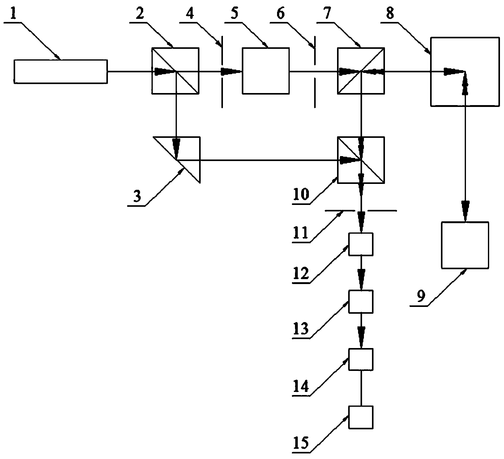
[0025] refer to figure 1 , The scanning laser vibration measurement system of the present invention comprises: a laser 1, a first dichroic prism 2, a reflective prism 3, a first diaphragm 4, an AO acousto-optic modulator 5, a second diaphragm 6, a second dichroic prism 7, two Dimensional scanning control system 8, beam combining mirror 10, third aperture 11, analyzer 12, photodetector 13, intermediate frequency amplifier 14 and signal processor 15, the laser beam is first divided into two beams in the system, and then combined, details as follows:

[0026] The laser 1 emits a laser beam, which is split by the first dichroic prism 2, and one of the beams is used as the local oscillator light of heterodyne detection and is reflected by the reflective prism 3 to the beam combining mirror 10 for beam combining;

[0027] The other light bea...


PUM


Abstract

The invention discloses a scanning laser vibration measurement system. A laser beam emitted by a laser passes through a first beam splitter prism to be split, where one path of the laser beam serves as local oscillator light for heterodyning detection to be reflected to a beam combiner through a reflection prism to be combined; the other path of the laser beam reaches a two-dimensional scanning control system through a first aperture, an AO modulator, a second aperture and a second beam splitter prism and then is emitted to a target, and scattered beams reach the beam combiner through the two-dimensional scanning control system and the second beam splitter prism to be combined with the local oscillator light; after the laser beams are combined, the combined laser beam reaches a signal processor through a third aperture, a polarization analyzer, a photoelectric detector and an intermediate frequency amplifier. The scanning laser vibration measurement system has the advantages that on the principle of heterodyning laser interference measurement, characteristics of vibration, speed and displacement of the target can be measured in a non-contact mode, and thus the scanning laser vibration measurement system is high in measurement precision and anti-interference capacity and the like; in the heterodyning detection, the design of receiving and transmitting integration and two-dimensional scanning measurement is adopted, and thus the scanning laser vibration measurement system is firm and compact in structure, convenient to measure and adjust and the like.

Description

technical field [0001] The invention relates to a measurement system, in particular to a scanning laser vibration measurement system, which belongs to the field of measurement technology. Background technique [0002] The existing measurement system mainly has the following problems: [0003] 1. The measurement distance is short, mostly within 30m; [0004] 2. The measurement vibration frequency range is narrow, mostly within 100 kHz; [0005] 3. Weak anti-interference ability, easily affected by ambient light; [0006] 4. The measurement accuracy is low. [0007] At present, optical detection mainly includes direct detection and heterodyne detection. The direct detection method has low measurement accuracy and poor anti-interference ability, while the heterodyne detection method has high measurement accuracy and strong anti-interference ability. However, the existing heterodyne measurement system usually detects an area of ​​the target or a point of the target, and does...

Claims


Application Information

Patent Timeline
Patent Type & Authority Applications(China)
IPC IPC(8): G01H9/00G01P3/36G01B11/02
Inventor 曹长庆曾晓东刘虎冯喆珺刘天航高新华曹星江党文佳
Owner XIDIAN UNIV
Why Eureka
Try Eureka