Electricity meter detection system

A detection system and electric meter technology, applied in the field of electric power, can solve the problems of reducing detection efficiency, consuming physical strength, inaccurate detection results, etc., and achieving the effects of improving safety performance, avoiding electric shock, and improving detection efficiency

Active Publication Date: 2014-07-02
BEIJIG YUPONT ELECTRIC POWER TECH
View PDF7 Cites 18 Cited by
  • Summary
  • Abstract
  • Description
  • Claims
  • Application Information

AI Technical Summary

Problems solved by technology

However, it has the following disadvantages: 1. The detection time is slow, and the replacement of the PCB board cannot be completed quickly. Communication detection still needs manual operation, which greatly reduces the detection efficiency; 2. The detection results are not accurate, and it is impossible to reserve time for each The power supply pins are tested and compared one by one. Whether the function of the metering part is normal can only be roughly judged by a single indicator light of the electric meter.
3. The risk is high, because the manual inspection can only power on the PCB with both hands, if there is a serious short circuit in the rear stage of the power supply, the isolation transformer in front cannot completely protect the inspector from being electrocuted.
4. The efficiency is low. It takes at least 1 and a half minutes to complete the detection of a meter by manual inspection, and one inspector can only detect one motherboard, which greatly reduces the detection efficiency
Compared with the manual detection method, this detection method does improve the detection efficiency, but this method requires some physical strength to press each PCB board by hand, and the demand for physical strength is relatively high, so it is not suitable for enterprises with large annual output; in addition, The test results are not detailed, and the test conclusions using this method are not listed one by one. After the test is completed, if it fails, it is necessary to gradually find the problem in the maintenance process, which greatly reduces the efficiency.
Secondly, when the tooling of this structure needs to disassemble multiple parts one by one and debug for a period of time when changing the detection scheme, it is necessary to continue the test of another product
Moreover, for most of the current smart card meters, the process of inserting and removing the card still needs to be manually operated.

Method used


Image

  • Electricity meter detection system
  • Electricity meter detection system
  • Electricity meter detection system

Examples


Embodiment Construction

[0031] In order to make the object, technical solution and advantages of the present invention clearer, the embodiments of the present invention will be further described in detail below in conjunction with the accompanying drawings. Here, the exemplary embodiments and descriptions of the present invention are used to explain the present invention, but not to limit the present invention.

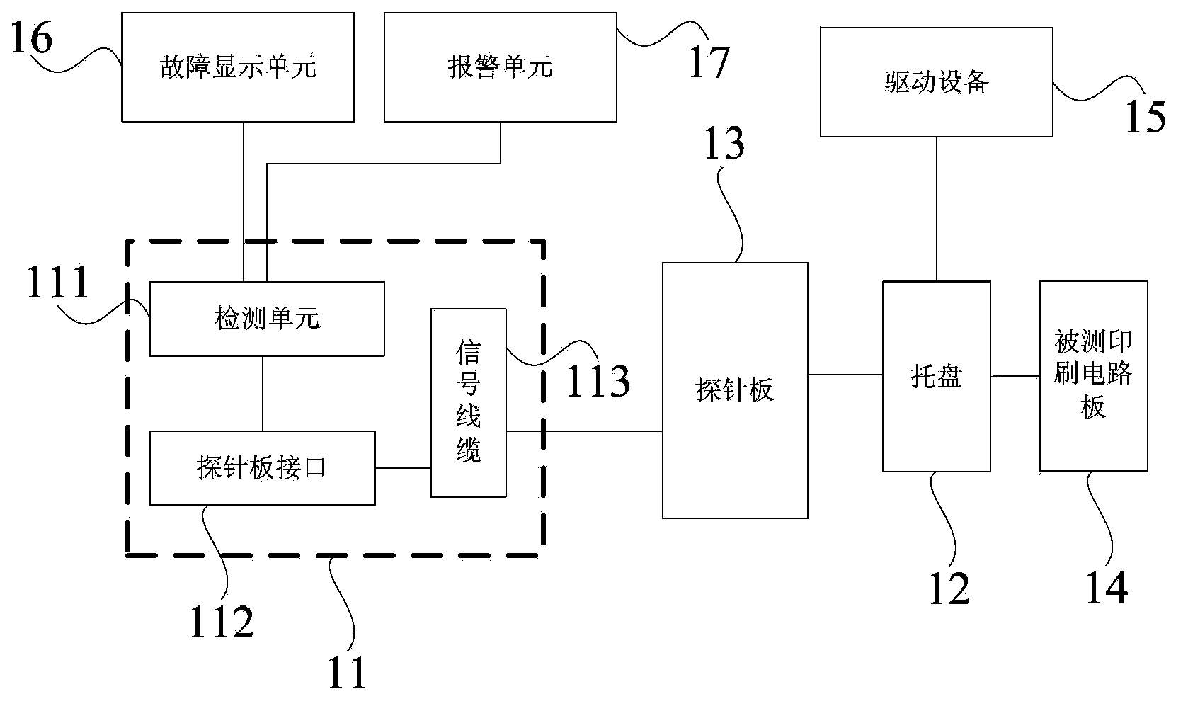
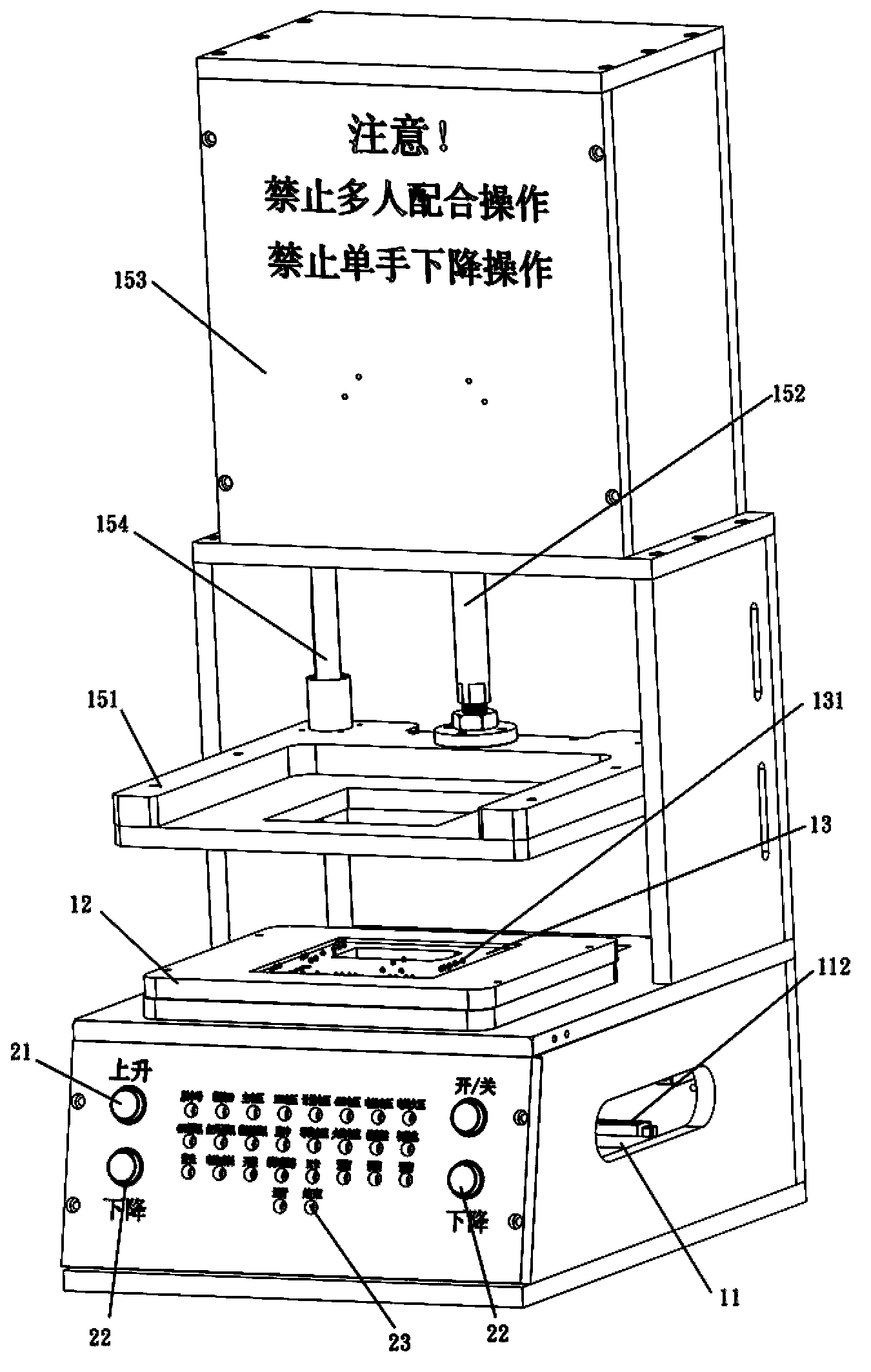
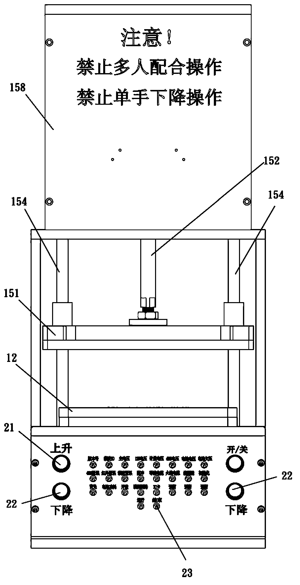
[0032] An embodiment of the present invention provides a meter detection system, such as Figure 1 to Figure 3 As shown, the system includes: a detection main board 11, a tray 12 and a probe card 13;

[0033] The detection main board 11 includes: a detection unit 111, a probe card interface 112 and a signal cable 113; the detection unit 111 is arranged on the board surface of the detection main board, and is electrically connected to the probe card interface 112; Preferably, the detection main board is a printed circuit board, the detection unit and the probe board interface are welded on t...


PUM


Abstract

The invention relates to the field of electric power, and particularly relates to an electricity meter detection system. The system comprises a detection mainboard, a pallet and a probe board. The detection mainboard comprises a detection unit, a probe board interface and a signal cable. The detection unit is arranged on the board surface of the detection mainboard and electrically connected with the probe board interface. The probe board interface is electrically connected with the probe board via the signal cable. The pallet is arranged right above the probe board and used for placing a printed circuit board to be detected so that one surface, which is provided with detection points, of the printed circuit board to be detected is enabled to orient the probe board. The probe board is provided with multiple probes. Each probe can be correspondingly contacted with the corresponding detection point on the printed circuit board to be detected on the pallet which is arranged right above the probe board. According to the electricity meter detection system, detection efficiency is substantially enhanced, and various personal injury situations like electric shock can be avoided by adopting the novel structure so that safety performance of the system is enhanced.

Description

technical field [0001] The invention relates to the field of electric power, in particular to an electric meter detection system. Background technique [0002] With the continuous development of the national economy, electricity has become the most important energy source in the country. As far as civilian electricity is concerned, due to the great abundance of people's material life and the rapid improvement of the quality of life, the demand for electricity is also increasing. However, the current management of residential electricity use is too backward. With the continuous development of residential electricity management, the country is gradually increasing its efforts in the construction of smart grids, and there are new updates to the production capacity and quality control capabilities of meter manufacturers. Strict requirements, most of the current production meters are single-phase smart meters of the national grid standard, and most of the mechanical meters have ...

Claims


Application Information

Patent Timeline
Patent Type & Authority Applications(China)
IPC IPC(8): G01R35/04
Inventor 杨晓琰韩振东李猛卢彦卿徐国库
Owner BEIJIG YUPONT ELECTRIC POWER TECH
Why Eureka
Try Eureka