Light guide plate, backlight module and display device
一种导光板、导光体的技术,应用在照明装置、固定照明装置、光学等方向,能够解决结构性能与光学效能不足等问题,达到整体结构性能与光学效能提升、提升光学辉度、增加强度的效果
- Summary
- Abstract
- Description
- Claims
- Application Information
AI Technical Summary
Problems solved by technology
Method used
Image
Examples
no. 1 example 〕
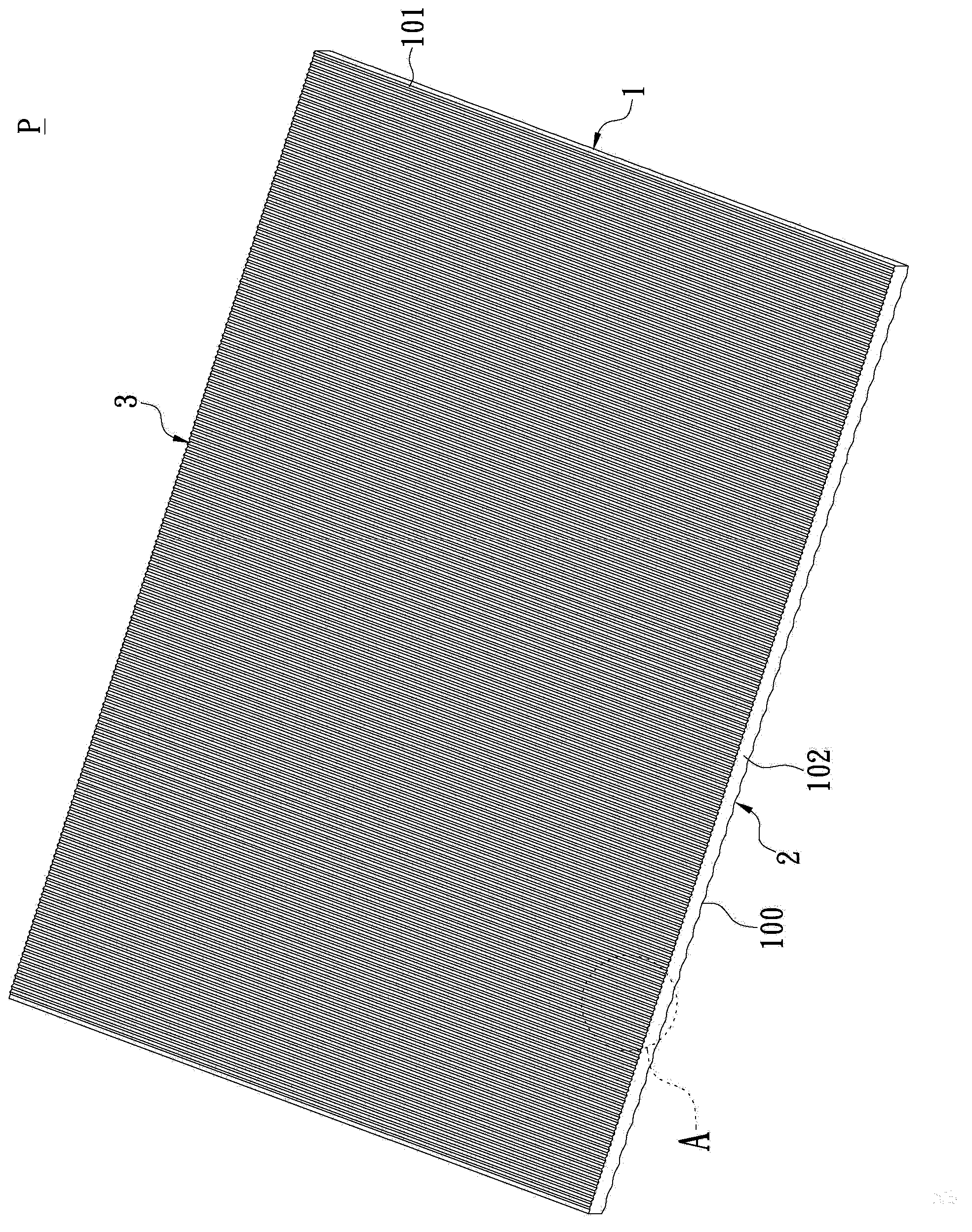
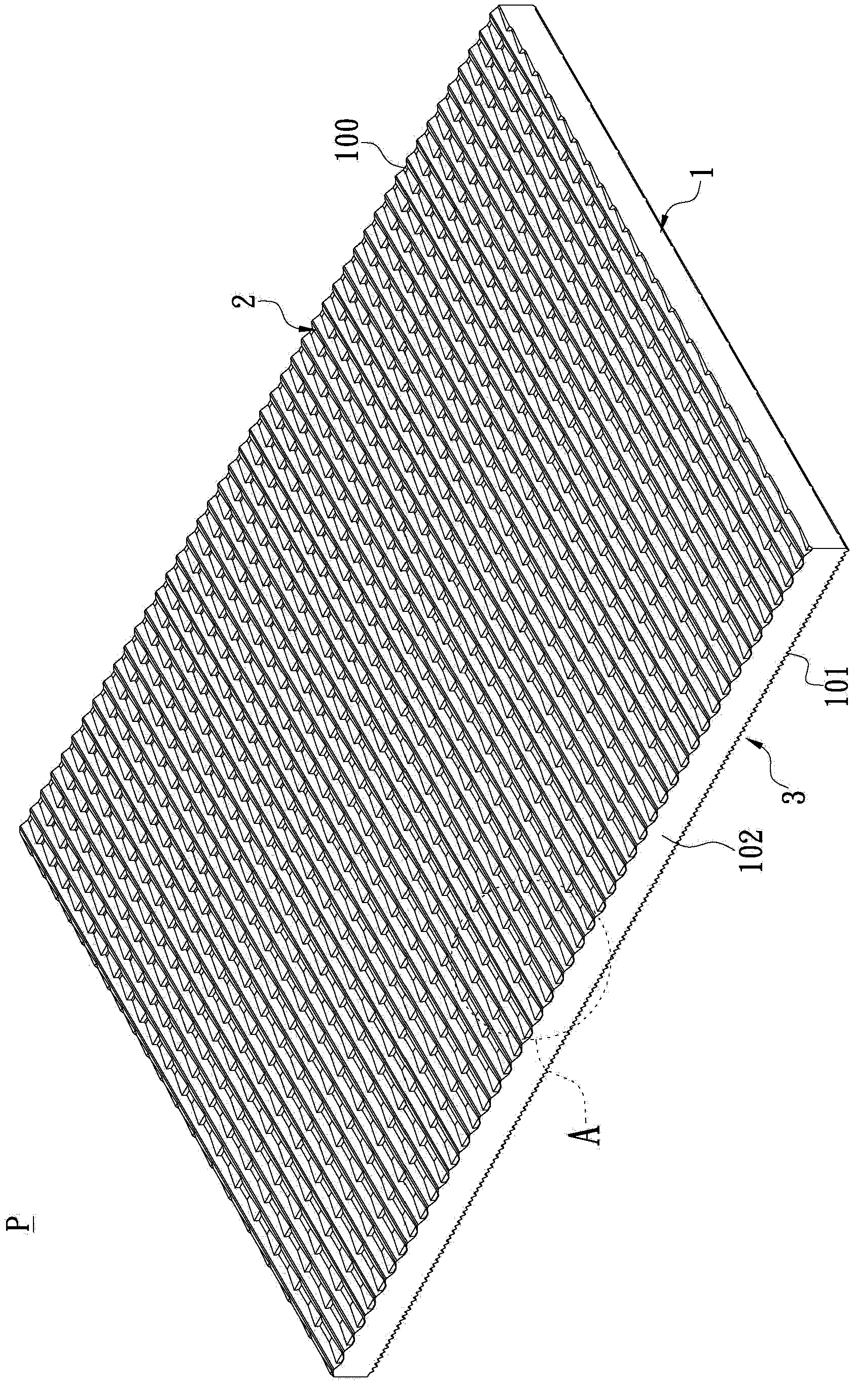
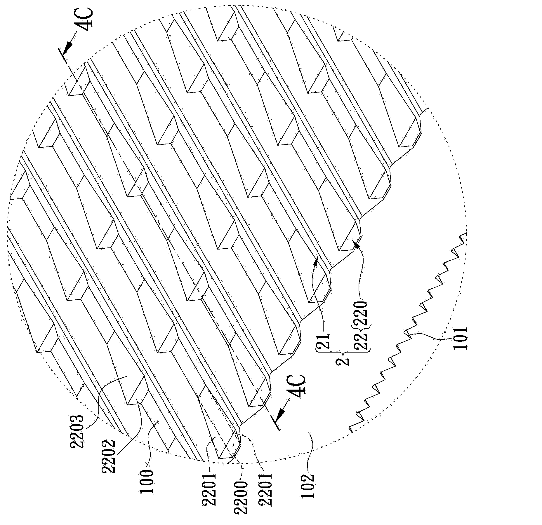
[0064] see figure 1 and figure 2 shown, where figure 1 is a three-dimensional schematic diagram of one of the viewing angles, figure 2It is a three-dimensional schematic diagram of another viewing angle. As can be seen from the above figures, the first embodiment of the present invention provides a light guide plate P, which includes: a light guide body 1, a first light guide unit 2 and a second light guide unit 3, wherein the light guide body 1 has A first surface 100 , a second surface 101 opposite to the first surface 100 , and a light incident surface 102 connected between the first surface 100 and the second surface 101 . Furthermore, according to different design requirements, the first surface 100 and the second surface 101 can be respectively a reflective surface and a light-emitting surface, or reversed, and the first surface 100 and the second surface 101 can be respectively a light-emitting surface and a reflective surface. noodle. In addition, according to d...
no. 2 example
[0085] see Figure 9 As shown, the second embodiment of the present invention provides a backlight module, which includes: a light guide plate P and a light emitting structure B, wherein the light emitting structure B is adjacent to the light incident surface 102, and the projected light beam L1 generated by the light emitting structure B can be obtained from The light incident surface 102 enters into the light guide body 1 . For example, when the first surface 100 and the second surface 101 are the reflection surface and the light exit surface respectively, the projected light beam L1 entering the light guide body 102 from the light incident surface 102 can be reflected by the first light guide unit 2 to form The light beam L2 is reflected, and the reflected light beam L2 can pass through the second light guide unit 3 to form a surface light source projected outward.
no. 3 example
[0087] see Figure 9 As shown, the third embodiment of the present invention provides a display device, which includes: a light guide plate P, a light emitting structure B and a display panel D. As shown in FIG. Wherein, the light emitting structure B is adjacent to the light incident surface 102 , and the projected light beam L1 generated by the light emitting structure B can enter the light guide body 1 from the light incident surface 102 . In addition, the display panel D is disposed above the light guide plate P, and the projected light beam L1 can pass through the light guide plate P to form a surface light source directed toward the display panel D. Referring to FIG. For example, when the first surface 100 and the second surface 101 are the reflection surface and the light exit surface respectively, the projected light beam L1 entering the light guide body 102 from the light incident surface 102 can be reflected by the first light guide unit 2 to form The light beam L2 ...
PUM
| Property | Measurement | Unit |
|---|---|---|
| radius | aaaaa | aaaaa |
| angle | aaaaa | aaaaa |
Abstract
Description
Claims
Application Information
 - R&D
- Intellectual Property
- Life Sciences
- Materials
- Tech Scout
- Unparalleled Data Quality
- Higher Quality Content
- 60% Fewer Hallucinations
Browse by: Latest US Patents, China's latest patents, Technical Efficacy Thesaurus, Application Domain, Technology Topic, Popular Technical Reports.
© 2025 PatSnap. All rights reserved.Legal|Privacy policy|Modern Slavery Act Transparency Statement|Sitemap|About US| Contact US: help@patsnap.com


