Quasi-sinusoidal winding linear motor

A linear motor and quasi-sine technology, applied in the direction of electrical components, electromechanical devices, electric components, etc., can solve the problems of high manufacturing cost, large motor thrust fluctuations, and increased copper consumption, and achieve low manufacturing costs, reduce thrust fluctuations, The effect that insulation is easy

Active Publication Date: 2017-04-12
HARBIN INST OF TECH
View PDF3 Cites 0 Cited by
  • Summary
  • Abstract
  • Description
  • Claims
  • Application Information

AI Technical Summary

Problems solved by technology

[0003] The purpose of the present invention is to solve the problems of the existing flat three-phase linear permanent magnet synchronous motor that the coil ends of the windings of each phase intersect each other, resulting in increased copper consumption, high manufacturing cost, and large fluctuations in the thrust of the motor, and provides a quasi- Sinusoidal winding linear motor

Method used


Image

  • Quasi-sinusoidal winding linear motor
  • Quasi-sinusoidal winding linear motor
  • Quasi-sinusoidal winding linear motor

Examples


specific Embodiment approach 1

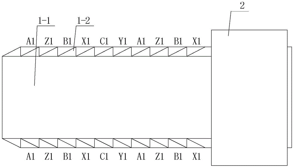
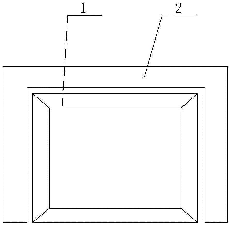
[0020] Specific implementation mode one: the following combination figure 1 , figure 2 , Figure 5 and Figure 6 Describe this embodiment, the quasi-sinusoidal winding linear motor described in this embodiment includes a primary 1 and a secondary 2, the secondary 2 is a single-sided, double-sided, three-sided or four-sided structure, the opposite surfaces of the primary 1 and the secondary 2 An air gap is formed between them; the primary 1 includes a primary iron core 1-1 and a primary winding 1-2, the cross section of the primary iron core 1-1 along the direction of relative movement is rectangular, and the side surface of the air gap of the primary iron core 1-1 is a smooth plane;

[0021] The primary winding 1-2 is an m-phase winding, and m is the number of phases of the motor; within the range of each pole pitch of the primary core 1-1, m winding coils are closely arranged in sequence along their relative motion direction, and each winding coil is rectangular. Surroun...

specific Embodiment approach 2

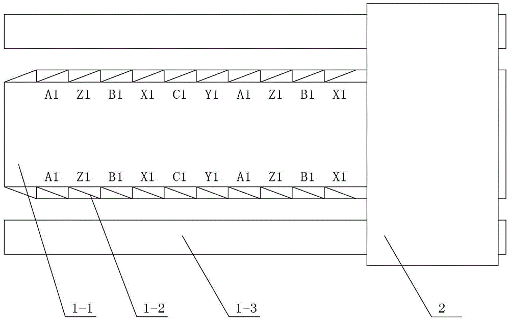
[0023] Specific implementation mode two: the following combination image 3 and Figure 4 Describe this embodiment. This embodiment will further explain Embodiment 1. The secondary 2 in this embodiment has a double-sided, three-sided or four-sided structure. The primary 1 also includes two auxiliary primary cores 1-3, two auxiliary primary cores 1-3 is symmetrically arranged on both sides of the primary core 1-1, placed in parallel with the primary core 1-1, and the two symmetrical secondary sides of the secondary 2 are respectively located on the primary core 1-1 and the corresponding auxiliary primary core 1 Between -3, air gaps are formed between the primary core 1-1 and the secondary 2 and between the auxiliary primary core 1-3 and the secondary 2, and the cross-section of the auxiliary primary core 1-3 along the direction of relative movement is rectangular.

[0024] In this embodiment, the auxiliary primary core 1-3 forms a part of the main magnetic circuit of the motor...

specific Embodiment approach 3

[0025] Specific implementation mode three: the following combination image 3 and Figure 4 Describe this embodiment. This embodiment will further explain Embodiment 1. The secondary 2 in this embodiment has a double-sided, three-sided or four-sided structure. The real wire motor also includes two auxiliary primary, and the two auxiliary primary mirrors are symmetrical Set on both sides of the primary core 1-1, placed in parallel with the primary core 1-1, the two symmetrical secondary sides of the secondary 2 are respectively located between the primary core 1-1 and the corresponding auxiliary primary, the primary core 1- Air gaps are formed between 1 and secondary 2 and secondary 2 and auxiliary primary; auxiliary primary includes auxiliary primary core and auxiliary primary winding, the cross-sections of auxiliary primary core and auxiliary primary winding are rectangular along their relative movement direction, auxiliary The arrangement of the auxiliary primary winding on...


PUM


Abstract

The invention discloses a quasi-sinusoidal winding linear motor and belongs to the technical field of linear motors. The quasi-sinusoidal winding linear motor aims to solve the problems that due to the mutual intersection of the ends of coils of all phases of windings, existing panel type three-phase linear permanent magnet synchronous motors are high in copper consumption, high in manufacturing cost and large in thrust ripple. According to the quasi-sinusoidal winding linear motor, a primary winding is an m-phase winding, wherein m is the phase of the motor; m winding coils are sequentially and closely arranged in the relative movement direction within each polar distance range of a primary iron core, each winding coil is rectangular and is wound around the outer surface of the primary iron core, the cross section of each winding coil in the winding direction is a parallelogram, and a quasi-sinusoidal structure is formed on the air gap side of the primary iron core; the arranging methods, within all the polar distance ranges of the primary iron core, of the m winding coils are the same, and all the winding coils on the primary iron core form an m-phase winding. The invention discloses the linear motor.

Description

technical field [0001] The invention relates to a quasi-sinusoidal winding linear motor and belongs to the technical field of linear motors. Background technique [0002] The armature core pitch τ of the traditional flat three-phase linear permanent magnet synchronous motor t The pole distance τ from the permanent magnet p Satisfy the relation 3τ t =τ p , a coil side is embedded in each slot, and the coil pitch is equal to the pole pitch. This winding structure is called an integer slot single-layer winding. The winding of the motor is as Figure 9 As shown, the coil side of the A-phase winding is embedded in the first slot and the fourth slot, while straddling the second slot and the third slot, and the coil side of the C-phase winding is placed in the second slot and the third slot. Embedded in the fifth slot, while straddling the third and fourth slots, and so on. The main problem of this type of winding is that the ends of the coils of each phase winding exposed out...

Claims


Application Information

Patent Timeline
Patent Type & Authority Patents(China)
IPC IPC(8): H02K41/03
Inventor 寇宝泉尹相睿谢逸轩陈宇声
Owner HARBIN INST OF TECH
Why Eureka
Try Eureka