
A multi-antenna transmission method based on sounding reference signal, terminal and base station

A technology for sounding reference signals and signal transmission, which is applied in the field of communication, and can solve problems such as difficulty in completely obtaining UE antennas, inability to match the wireless channel between UE antennas and base station antennas, etc.

Active Publication Date: 2017-12-19
ADVANCED STANDARD COMM LLC
View PDF6 Cites 0 Cited by
  • Summary
  • Abstract
  • Description
  • Claims
  • Application Information

AI Technical Summary

Problems solved by technology

[0007] The technical problem solved by the present invention is to provide a multi-antenna transmission method based on sounding reference signals, a terminal and a base station, and solve the problem that in the prior art, when the number of receiving antennas of the UE is greater than the number of transmitting ports and the number of downlink configuration ports is greater than 2, the eNB calculates according to the uplink channel matrix The downlink precoding cannot match the wireless channel between all UE antennas and base station antennas, and it is difficult for the eNB to fully obtain the wireless channel conditions from all antennas of the UE to the eNode B when the number of transmit antennas available to the UE is greater than the number of transmit ports, and the PUSCH cannot pass through the most Optimum Antenna or Antenna Group to Send Questions

Method used


Image

  • A multi-antenna transmission method based on sounding reference signal, terminal and base station
  • A multi-antenna transmission method based on sounding reference signal, terminal and base station
  • A multi-antenna transmission method based on sounding reference signal, terminal and base station

Examples


Embodiment Construction

[0064] In order to make the objectives, technical solutions, and advantages of the present invention clearer, the embodiments of the present invention will be described in detail below with reference to the accompanying drawings. It should be noted that the embodiments in the application and the features in the embodiments can be combined with each other arbitrarily if there is no conflict.

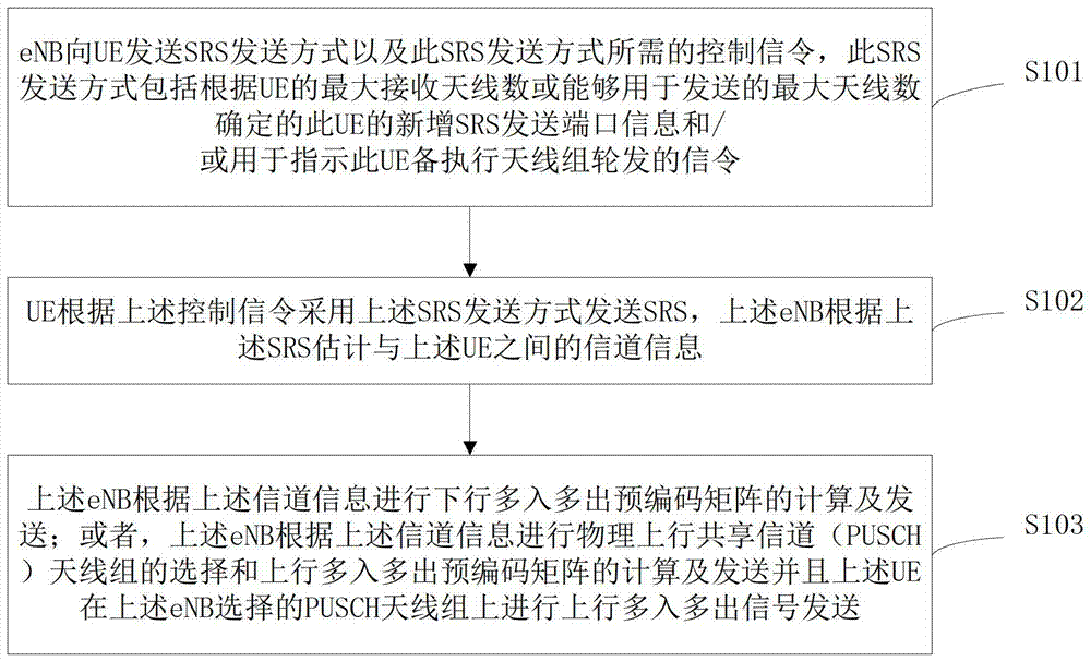
[0065] Such as figure 1 As shown, the multi-antenna signal transmission method based on sounding reference signals in the present invention includes steps S101 to S103.

[0066] Step S101: The eNB sends the SRS transmission mode and the control signaling required by the SRS transmission mode to the UE. The SRS transmission mode includes the addition of the UE determined according to the maximum number of receiving antennas of the UE or the maximum number of antennas that can be used for transmission. SRS transmission port information and / or signaling used to instruct the UE to perform antenna ...


PUM


Abstract

The invention discloses a multi-antenna transmission method according to a sounding reference signal, a terminal and a base station. An eNB transmits to a UE a RS including newly added SRS transmission port information and / or signaling used to instruct the UE to perform antenna group rotation. The transmission mode and the control signaling required by the SRS transmission mode, the UE transmits the SRS in the above SRS transmission mode, and the eNB estimates the channel information according to the SRS, and calculates and transmits the precoding matrix. The present invention can overcome the problem that the downlink precoding calculated by the eNB according to the uplink channel matrix cannot match the wireless channels between all UE antennas and base station antennas when the number of UE receiving antennas is greater than the number of transmitting ports and the number of downlink configuration ports is greater than 2; and the UE can be used to transmit When the number of antennas is greater than the number of transmission ports, it is difficult for the eNB to fully obtain the wireless channel conditions from all antennas of the UE to the eNB, and the PUSCH cannot be transmitted through the optimal antenna or antenna group.

Description

Technical field [0001] The present invention relates to the field of communications, in particular to a multi-antenna transmission method, terminal and base station based on sounding reference signals. Background technique [0002] Multiple-Input Multiple-Out-put (MIMO) precoding technology is divided into codebook-based precoding and non-codebook-based precoding. In contrast, non-codebook-based precoding can better match channels and improve link performance. The beamforming technology adopted by the Long Term Evolution (LTE) Time Division Duplexing (TDD) system is a non-codebook-based precoding technology. [0003] Beamforming is a method of obtaining beamforming receiving / transmitting weights by estimating the spatial channel through which the received signal propagates. In the receiving / transmitting process, the input and output signals of each antenna in the array are weighted to realize the signal beam Shaped receiving / sending. [0004] The LTE TDD mode adopts the time divis...

Claims


Application Information

Patent Timeline
Patent Type & Authority Patents(China)
IPC IPC(8): H04B7/06H04L1/00H04L1/06
CPCH04B7/0486H04B7/0617H04B7/0456H04L5/005H04L5/0094H04L5/0007H04W72/23H04W74/004H04W88/08
Inventor 黄琛赵亚军莫林梅徐汉青孙宝玉李玉洁秦洪峰陈国峰袁红峰张新
Owner ADVANCED STANDARD COMM LLC
Learn More