
Microdiaphragm pump

A micro-diaphragm pump and diaphragm technology, used in pumps, pump components, variable-capacity pump components, etc., can solve problems such as difficulty in increasing fluid attraction and discharge force, small change in pressure chamber volume, and incorrect discharge management. problems, to achieve the effect of improving production efficiency, increasing volume change, and good productivity

Inactive Publication Date: 2014-07-02
KIKUCHI SEISAKUSHO CO LTD
View PDF13 Cites 8 Cited by
  • Summary
  • Abstract
  • Description
  • Claims
  • Application Information

AI Technical Summary

Problems solved by technology

For this reason, there is a problem that the volume change of the pressure chamber due to the vibration of the diaphragm becomes small, it is difficult to smooth the suction / discharge of the fluid, and the management of the discharge amount per stroke of the diaphragm is not correct.
For this reason, it is difficult or impossible to use for compressible gases, etc.
Furthermore, since the area of ​​the diaphragm is small, it is difficult to increase the suction force and discharge force of the fluid.
Furthermore, there is also a problem that the silicon substrate used here is relatively expensive.

Method used


Image

  • Microdiaphragm pump
  • Microdiaphragm pump
  • Microdiaphragm pump

Examples


Embodiment 1

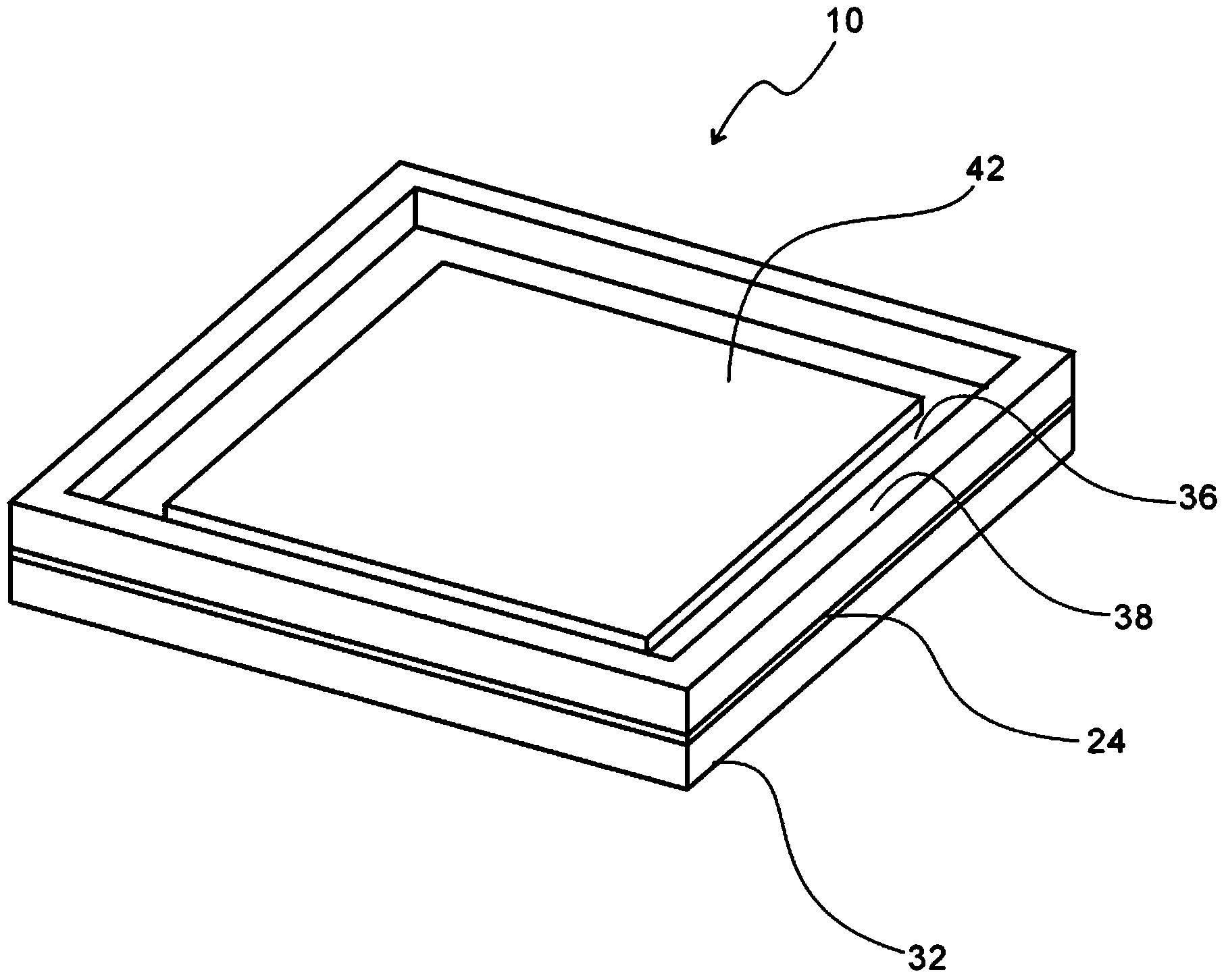
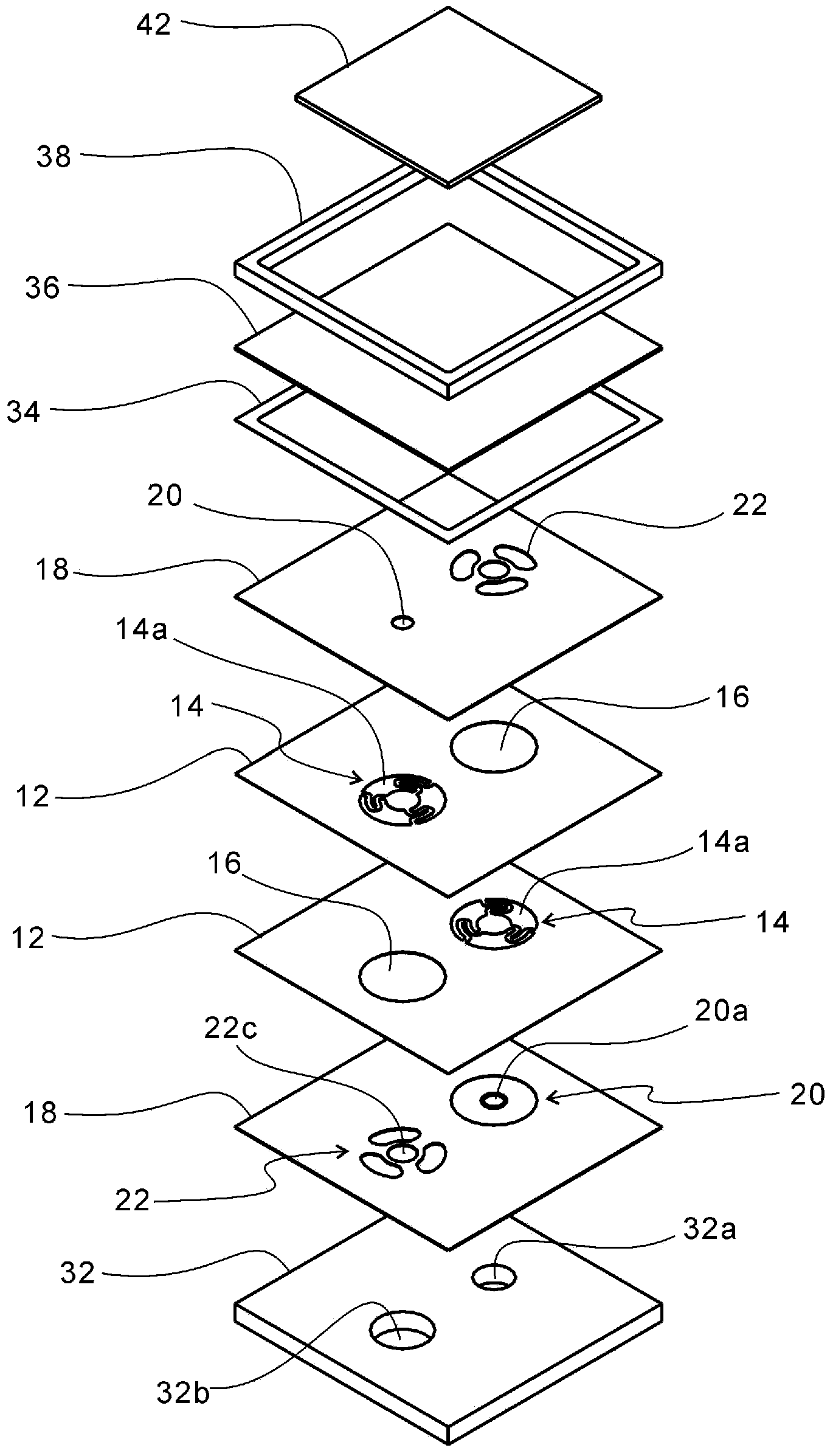
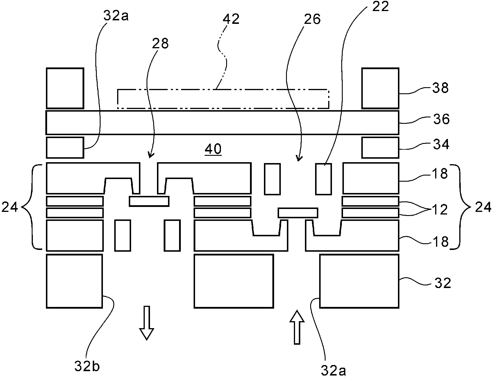
[0036] Figure 1~4 Among them, symbol 10 is the micro-diaphragm pump related to the present invention. The pump 10 is a pump in which a plurality of stainless thin metal plates and a frame are laminated and bonded, that is, the metal thin plates are aligned, stacked and bonded, and has a square shape of about 7 to 10 mm on one side. 12 is the valve plate sheet, such as Figure 5 Shown is a valve plate sheet in which a valve plate 14 and flow path openings 16 are formed on a stainless thin plate with a thickness of 0.01 mm (10 microns) by etching and press-cutting. Here, the valve plate 14 is held by a support arm 14 b that extends while being bent toward the inner diameter side from a valve plate opening 14 a having substantially the same diameter as the flow path opening 16 .

[0037] 18 is a valve seat sheet, such as Image 6 Shown is a valve seat sheet in which a valve seat 20 and a valve stopper 22 are formed on a stainless thin plate with a thickness of 0.05 mm by etch...


PUM


Abstract

A microdiaphragm pump having a diaphragm chamber in contact with one side of an intake valve and one side of a discharge valve. The microdiaphragm includes two valve plate sheets 12, in each of which a valve plate 14 of one of an intake valve 26 and a discharge valve 28 and a flow path aperture 16 that provides a passage of the other valve are formed and which are laminated in directions that are opposite from each other; two valve seat sheets 18, which are laminated to the laminate and in which valve seats 20 and valve stoppers 22 are formed; a base plate 32; a frame 34; a diaphragm 36; and a drive element 42. The microdiaphragm pump has extremely small external dimensions and provides high productivity, high flow control accuracy, a smooth operation, large suction and discharge forces, and high reliability.

Description

technical field [0001] This invention relates to a microdiaphragm pump formed by laminating and bonding a plurality of thin metal plates on which a valve plate, a valve seat, a diaphragm, etc. are patterned. Background technique [0002] In recent years, the popularization and commercialization of fuel cell systems are expected to be used as distributed energy devices for households (detached houses). Such a fuel cell requires a pump for supplying fuel gas, liquid fuel, water supplied to the reformer, hydrogen generated in the reformer, and the like to the fuel cell itself. In addition, after removing the necessary hydrogen (H 2 ) modification, carbon monoxide (CO) is generated, but since this carbon monoxide adversely affects the performance of the battery catalyst, in order to reduce the concentration of carbon monoxide, it is required to also control the flow rate of air for selective oxidation. In addition, in analytical devices and medical-related items (medicine, cli...

Claims


Application Information

Patent Timeline
Patent Type & Authority Applications(China)
IPC IPC(8): F04B43/02F04B43/04F04B45/04F04B45/047
CPCF04B43/046F04B43/043F04B43/073F04B53/16F04B53/10F05B2210/11
Inventor 椛泽康成光部崇
Owner KIKUCHI SEISAKUSHO CO LTD
Learn More