Split electrode electrosparking method and adopted split electrode

A processing method and EDM technology, applied in the field of split electrodes, can solve the problems of high technical difficulty, high scrap rate, tool rigidity and space limitation, etc., and achieve the effect of simple processing trajectory, guaranteed processing accuracy, and reduced programming difficulty

Active Publication Date: 2014-07-09
DIMON BEIJING CNC TECH +1
View PDF6 Cites 12 Cited by
  • Summary
  • Abstract
  • Description
  • Claims
  • Application Information

AI Technical Summary

Problems solved by technology

However, when machining impellers with small channels made of difficult-to-machine materials, CNC milling is difficult to apply due to tool rigidity and space constrain

Method used


Image

  • Split electrode electrosparking method and adopted split electrode
  • Split electrode electrosparking method and adopted split electrode
  • Split electrode electrosparking method and adopted split electrode

Examples


Embodiment 1

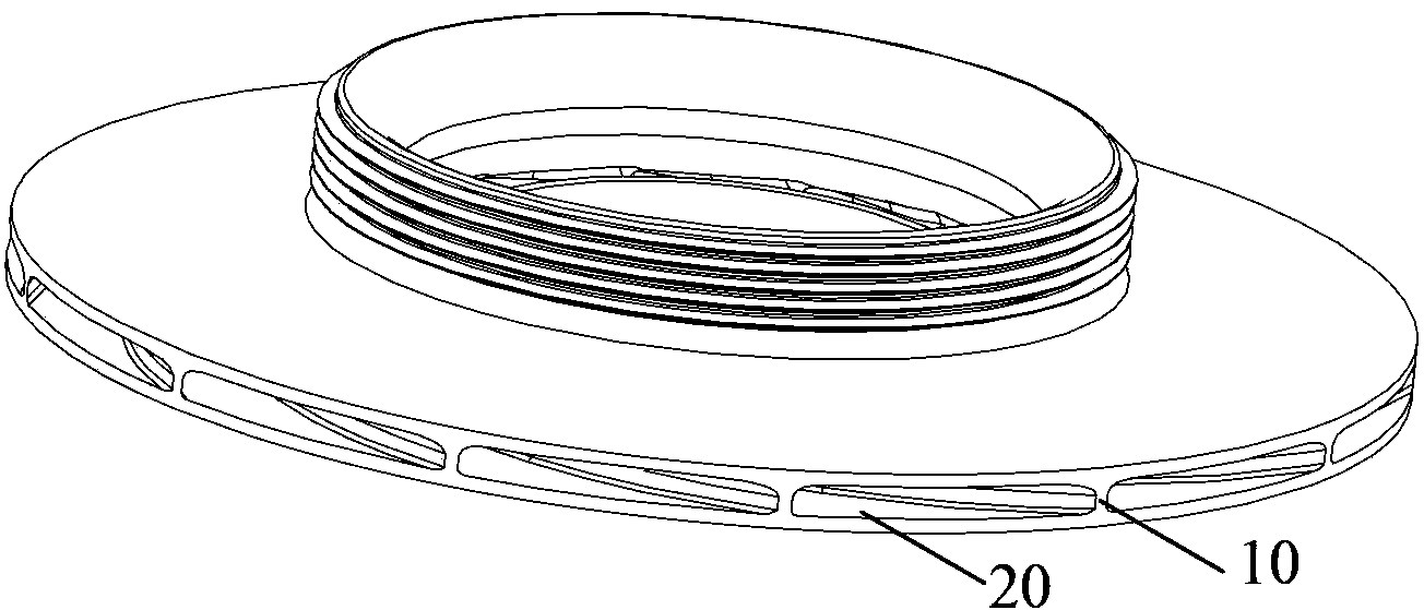
[0029] EDM uses the instantaneous high temperature generated by the discharge to melt the surface of the workpiece opposite to the electrode, and gradually remove the material to achieve the purpose of processing. Therefore, this embodiment adopts the split electrode EDM method to prepare the integral closed impeller, so as to figure 1 The overall closed impeller structure shown is taken as an example to describe the specific implementation of the split electrode electric discharge machining method.

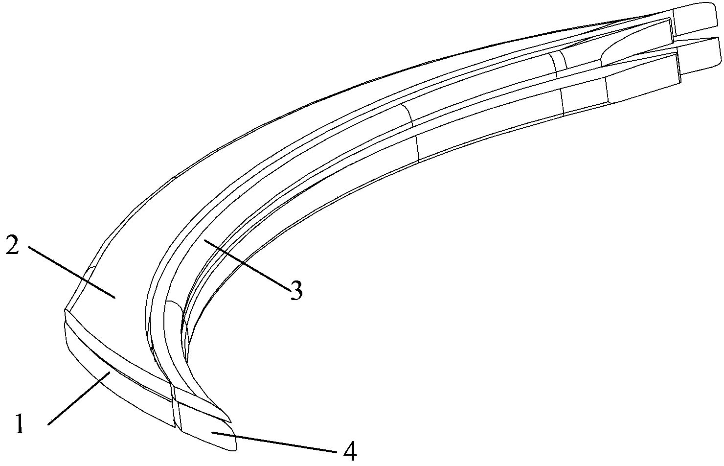
[0030] First, according to figure 1 The internal cavity structure of the overall closed impeller shown, that is, the shape and size, is extracted as figure 2 The three-dimensional model of a single flow channel inside the overall closed impeller shown, the single flow channel is figure 1 As shown in , the single flow channel 20 between two adjacent blades 10; because the shape and size of the multiple flow channels inside the integral closed impeller are exactly the same, so e...

Embodiment 2

[0038]This embodiment provides a split electrode used in Embodiment 1. The split electrode includes a plurality of single electrodes, and the number of single electrodes is equal to the number of modules formed by dividing the three-dimensional model of a single flow channel. A single electrode is divided into modules by EDM and its corresponding single flow channel. On the premise that there are four flow channel modules in Example 1, this embodiment sets the single electrode to four, and the four single electrodes correspond to the processing The four modules split by the single-channel 3D model. The four single electrodes are processed according to the characteristics of the flow channel cavity, and the external contour surface of the entity composed of all the single electrodes is highly consistent with the cavity of the closed impeller flow channel.

[0039] Corresponding to the four modules in Embodiment 1, there are four single electrodes, namely the first electrode, th...


PUM

PropertyMeasurementUnit
Gap widthaaaaaaaaaa
Thicknessaaaaaaaaaa

Abstract

The invention belongs to the field of non traditional machining and discloses a split electrode electrosparking method which includes the following steps: extracting a three-dimensional model of a single flowing channel in a whole enclosed impeller according to the shape and the size of a cavity in the whole enclosed impeller; zooming the three-dimensional model of the single flowing channel, conducting area partitioning on the zoomed three-dimensional model to divide the model into a plurality of modules; conducting electrosparking on an electrode that each module corresponds to according to the shape and the size of the module to form the single flowing channel consistent with the three-dimensional model before zooming, and conducting electrosparking on other flowing channels. By means of the method, various materials difficult to machine can be machined with high efficiency and high accuracy, the electrodes are small in size, and sufficient space is acquired for retreating and avoiding of the electrodes, so that the whole enclosed impeller with the small flowing channel cavity and complex space structure can be machined. The machining track of each split electrode is simple, programming difficulty is reduced, and machining accuracy is ensured.

Description

technical field [0001] The invention relates to the field of special processing, in particular to a split electrode electric discharge machining method and the split electrode used. Background technique [0002] As a high-tech, high-value-added component, the impeller is widely used in hydraulic machinery and air labor equipment, and its processing and manufacturing technology directly affects the working performance and reliability of the unit. In order to be able to adapt to the harsher working environment, the application of integral closed impellers with special materials is becoming more and more extensive. The overall closed structure and special materials (such as high-temperature alloys, titanium alloys, etc.) make its processing and manufacturing difficult. At present, CNC milling and precision casting are widely used in the processing of impellers. However, when machining impellers with small channels made of difficult-to-machine materials, CNC milling is difficu...

Claims


Application Information

Patent Timeline
IPC IPC(8): B23H9/00
Inventor 刘建勇伏金娟李艳任连生杨立光
Owner DIMON BEIJING CNC TECH
Why Eureka
Try Eureka