
Bottom structure of vertical corrugated bulkhead of ship

A bottom structure and trough-shaped bulkhead technology, which is applied to hull bulkheads, hull parts, and double-bottom hulls, can solve the problems of difficult construction and installation, increased empty ship weight, and high steel consumption, so as to increase ship loading. The effect of reducing the weight of the ship, reducing the weight of the ship, and increasing the capacity of the ship

Inactive Publication Date: 2014-07-09
谢合清
View PDF5 Cites 13 Cited by
  • Summary
  • Abstract
  • Description
  • Claims
  • Application Information

AI Technical Summary

Problems solved by technology

[0004] In order to overcome the disadvantages of traditional vertical trough-shaped bulkheads such as complex pier structure, high steel consumption, difficulty in construction and installation, occupying the tank capacity and increasing the weight of the empty ship, the present invention provides a bottom structure at the vertical trough-shaped bulkhead Technical solution, the bottom structure of this kind of vertical trough bulkhead not only saves the traditional lower pier structure, but also reduces the weight of the empty ship and the difficulty of construction, saving costs and improving operational efficiency

Method used


Image

  • Bottom structure of vertical corrugated bulkhead of ship
  • Bottom structure of vertical corrugated bulkhead of ship
  • Bottom structure of vertical corrugated bulkhead of ship

Examples


Embodiment

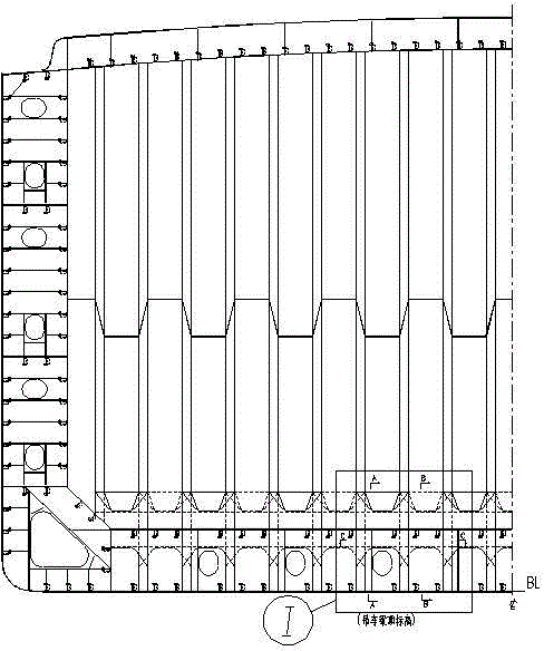
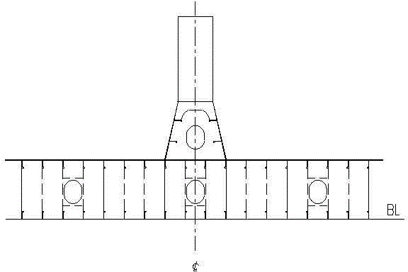
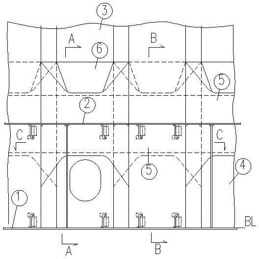
[0021] see Figure 1 to Figure 8 , a bottom structure of a vertical grooved bulkhead of a ship, comprising a bottom plate 1, an inner bottom plate 2, a vertical grooved bulkhead 3, a grooved rib 4, a U-shaped bracket 5, a grooved sealing plate 6, a short longitudinal girder 7, U-shaped plate reinforcement rib 8, inner bottom longitudinal bone 9, bottom plate longitudinal bone 10.

[0022] It is characterized in that a grooved rib 4 with the same cross-section as the vertical grooved bulkhead 3 is arranged between the bottom plate 1 and the inner bottom plate 2, and a U-shaped opening with a U-shaped mouth facing down is installed at the upper end of the grooved rib 4. The brackets 5, the inner bottom longitudinals 9 and the bottom plate longitudinals 10 are provided with matching passage holes, and the U-shaped brackets 5 with U-shaped openings facing upwards are installed at the grooved openings at the lower end of the vertical grooved bulkhead 3. The near U-shaped edge of t...


PUM


Abstract

A bottom structure of a vertical corrugated bulkhead of a ship is characterized in that corrugated rib plates identical to the section of the corrugated bulkhead in shape are mounted and welded between a ship bottom plate and an inner bottom plate and at corresponding rib positions of the corrugated bulkhead to replace traditional planar solid rib plates, transitional reinforcement U-shaped toggle plates are mounted and welded at openings of notches at the upper ends of the corrugated rib plates and the lower end of the vertical corrugated bulkhead, U-shaped sides of the U-shaped toggle plates above the inner bottom plate are welded to a corrugated seal plate which functions in sealing the U-shaped toggle plates and facilitating cabin cleaning and serves as a discharging plate on a bulk freighter, U-shaped sides of the U-shaped toggle plates below the inner bottom plates are free sides, and horizontal reinforcement rib plates are welded close to the U-shaped sides of the U-shaped toggle plates. By mounting and welding the U-shaped toggle plates at the upper ends of the corrugated rib plates and the lower end of the vertical corrugated bulkhead, stress at the welding joint of the vertical corrugation bulkhead and the inner bottom plate is reduced while stress concentration is eliminated, and the corrugated rib plates can be thinned properly as compared with the corrugated bulkhead.

Description

technical field [0001] The invention belongs to the technical field of ship structures, and relates to a technical proposal for a bottom structure at a vertical groove bulkhead of a ship. Background technique [0002] The corrugated bulkheads of ships have two structural forms: vertical and horizontal. Due to the characteristics of simple structure, excellent mechanical properties and easy cleaning, the corrugated bulkhead is widely used in the three main ship types of bulk carriers, container ships and oil tankers. The traditional vertical corrugated bulkhead is , the reason for the alignment and connection requirements of the bottom structure, pier structures are arranged on the upper and lower parts of the corrugated bulkhead. Since the bottom of the bulkhead bears the greatest force, and the trough-shaped bulkhead panel needs to be connected to the two ribs adjacent to the bottom, it is necessary to set the lower pier of the trapezoidal structure (see Figure 9 ), where...

Claims


Application Information

Patent Timeline
IPC IPC(8): B63B3/56B63B3/62
Inventor 谢合清
Owner 谢合清
Learn More