
Tensile sample deformation measurement method based on digital image correlation

A technology for tensile samples and measurement methods, which is applied in the direction of measuring devices, instruments, scientific instruments, etc., can solve problems such as tracking accuracy decline, image interference, and mark point deformation, so as to improve measurement speed and accuracy, simplify operation procedures, Avoid Specimen Marking Effects

Inactive Publication Date: 2014-07-09
JINAN SHIDAI SHIJIN TESTING MACHINE GRP
View PDF5 Cites 19 Cited by
  • Summary
  • Abstract
  • Description
  • Claims
  • Application Information

AI Technical Summary

Problems solved by technology

[0003] At present, the method of adding markers on the surface of the sample is relatively common in the scientific research and product fields. Combined with the image edge method, a clear and high-contrast sample image can be obtained, and the deformation of the sample can be measured through the displacement of the marker. The image The interference is small and the processing speed is fast, but considering that the deformation between the markers does not really represent the deformation of the sample itself, and the blessing itself brings a lot of work to the staff, artificial marking points gradually came into being. The surface is marked with high-contrast marking points to achieve deformation measurement. However, on the one hand, the marking points will increase the complexity of the operation. On the other hand, the requirements for the marking points themselves are relatively high, and the marking points themselves will also be deformed during the stretching of the material. , leading to a decrease in tracking accuracy

Method used


Image

  • Tensile sample deformation measurement method based on digital image correlation
  • Tensile sample deformation measurement method based on digital image correlation
  • Tensile sample deformation measurement method based on digital image correlation

Examples


Embodiment Construction

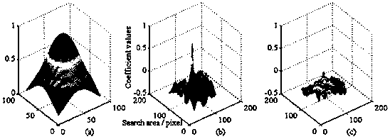
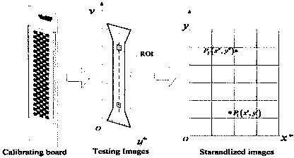
[0029] The digital image correlation-based tensile sample deformation measurement method of the present invention, in the video extensometer, in order to realize the high-speed precision measurement of the tensile sample deformation and simplify the previous sample marking method, the present invention focuses on using the image correlation method, combined with The measurement method based on the reference plane realizes the high-speed and high-precision measurement of the sample. It overcomes the shortcoming that the overall measurement accuracy of the system is limited in the traditional video extensometer measurement method. Such as figure 1 As shown, the algorithm implementation of this method is mainly divided into three parts, 1. Integer pixel positioning based on image correlation; 2. Sub-pixel positioning based on two-dimensional surface fitting; 3. Image mapping positioning based on reference plane. The organic combination of the three constitutes the main body of t...


PUM


Abstract

The invention provides a tensile sample deformation measurement method based on digital image correlation. The tensile sample deformation measurement method mainly applies an image correlation method and combines a measurement method based on a standard surface to realize high-speed and high-precision measurement of a test sample. The tensile sample deformation measurement method comprises the following steps: 1, carrying out integer pixel positioning based on the image correlation; 2, carrying out sub pixel positioning based on two-dimension curved surface fitting; and 3, carrying out image mapping positioning based on the standard surface. The three steps are organically combined to form a main body of the whole method. The tensile sample deformation measurement method has the beneficial effects that a standard plane mapping method is combined by adopting a simplified digital image correlation method so that the test sample is prevented from being marked; an operation flow is simplified, the measurement speed and the precision of the deformation of the test sample are improved, and the practicability of the system is improved.

Description

technical field [0001] The invention belongs to the field of digital image measurement of material deformation, and in particular relates to a method for measuring deformation of tensile samples based on digital image correlation. Background technique [0002] At present, according to the current situation of video extensometer, the measurement of sample deformation can be mainly divided into three methods, namely clamping markers, marking method and measurement method based on the texture characteristics of the sample itself. [0003] At present, the method of adding markers on the surface of the sample is relatively common in the scientific research and product fields. Combined with the image edge method, a clear and high-contrast sample image can be obtained, and the deformation of the sample can be measured through the displacement of the marker. The image The interference is small and the processing speed is fast, but considering that the deformation between the markers...

Claims


Application Information

Patent Timeline
IPC IPC(8): G01N3/06G01B11/16
Inventor 刘维平
Owner JINAN SHIDAI SHIJIN TESTING MACHINE GRP
Learn More