
Modularized rock core component spectral imaging scanning system

A spectral imaging and modular technology, applied in the field of optics, can solve problems such as limited spatial resolution of point spectra, difficulty in interpreting mineral components, and low spatial resolution

Inactive Publication Date: 2014-07-09
INST OF REMOTE SENSING & DIGITAL EARTH CHINESE ACADEMY OF SCI
View PDF7 Cites 12 Cited by
  • Summary
  • Abstract
  • Description
  • Claims
  • Application Information

AI Technical Summary

Problems solved by technology

These research results show that hyperspectral remote sensing technology has broad application prospects in the field of geology and mineral resources, but conventional hyperspectral remote sensing images are not suitable for core samples due to their low spatial resolution (30 meters); A core scanning system based on a non-imaging point spectrometer is developed. Typical systems such as the development system of the Nanjing Geological Survey Center and the HyLogger core spectral scanning system in Australia, but because the point spectrum can only space the core at a certain distance Acquisition cannot interpret the continuous and complete spectral information of the core surface, and the spatial resolution of the point spectrum is limited. What is scanned is the mixed spectrum of mineral components, which brings certain difficulties and uncertainties to the interpretation of mineral components.
A high-resolution imaging spectrometer for core samples has not been reported

Method used


Image

  • Modularized rock core component spectral imaging scanning system

Examples


Embodiment 1

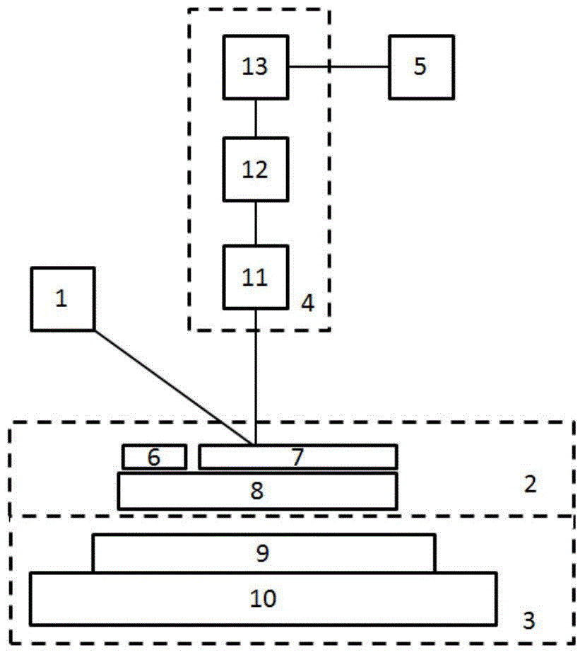
[0031] Such as figure 1 As shown, this embodiment provides a modular core component spectral imaging scanning system, including: a light source unit 1, a sample unit 2, and a spectrometer unit 4;

[0032] The wide-spectrum light beam emitted by the light source unit 1;

[0033] The sample unit 2 carries a core sample;

[0034] The wide-spectrum light beam emitted by the light source unit 1 evenly irradiates the scanning line area of ​​the rock core sample carried by the sample unit 2, and the diffuse reflection light of the rock core sample enters the spectrometer unit 4, and the spectrometer unit 4 according to The incident diffuse reflected light is used for spectral imaging.

[0035] optional, such as figure 1 shown, also includes:

[0036] Shifting unit 3, described shifting unit 3 comprises displacement platform 9, base 10, and described displacement platform 9 is positioned on described base 10, and described displacement platform 9 carries described sample unit 2, m...

Embodiment 2

[0054] Such as figure 1As shown, this embodiment provides a modular rock core component spectral imaging scanning system, including a light source unit 1, a sample unit 2, a shift unit 3, a spectrometer unit 4, and a computer 5; the light emitted by the light source unit 1 passes through The sample unit 2 enters the spectrometer unit 4 after reflection.

[0055] The sample unit 2 includes a whiteboard 6, a core tank, a core sample 7, and an adapter plate 8. The whiteboard 6 requires as high a reflectance as possible to correct the spectral inhomogeneity of the light source 1; the core tank is used to hold the core sample ; There can be 5 grids, 6 grids, 7 grids or other specifications according to different drill bit sizes; the adapter plate 8 fixes the whiteboard 6 and the core groove and the core sample 7 to the displacement table 9 of the displacement unit 3 .

[0056] The displacement unit 3 is composed of a displacement platform 9 and a base 10. The displacement platform...


PUM


Abstract

The invention discloses a modularized rock core component spectral imaging scanning system, which comprises a light source unit, a sample unit, and a spectrometer unit; the light source unit emits a light beam with a wide spectral line; the sample unit bears a rock core sample; the rock core sample born on the sample unit are uniformly exposed in the light beam with a wide spectral line emitted by the light source unit; light generated by diffuse reflection of the rock core sample enters the spectrometer unit; and the spectrometer unit performs spectral imaging according to the entered diffuse reflection light. Through the rock core component imaging spectra formed by the combination of image scanning technology with spectral light splitting technology, the modularized rock core component spectral imaging scanning system of embodiments of the invention not only provides the spatial form distribution of the rock core sample, but also provides sample spectral information accurate to pixel points in the imaging field of view, can assist in mineral identification, analysis, result visualization and post-treatment, and provides a new experimental platform for rock core mineral component analysis.

Description

technical field [0001] The invention relates to the field of optics, in particular to a modular rock core component spectral imaging scanning system. Background technique [0002] In geological prospecting work, core drilling is an indispensable and important link, which plays a decisive role in determining the grade and reserves of mineral resources. With the development of mineral resources, the process of deep prospecting has been accelerated, the drilling has become deeper and deeper, and the number of core samples has doubled. Not only the technical requirements for drilling are getting higher and higher, but also the technical requirements for core component analysis are getting higher and higher. [0003] Traditional core component analysis uses image scanners or X-ray core scanning technology to obtain core sample surface image information or three-dimensional images inside the core, but it is still difficult to analyze core samples only based on core sample surface...

Claims


Application Information

Patent Timeline
Patent Type & Authority Applications(China)
IPC IPC(8): G01N21/25G01N21/27
Inventor 张立福吴太夏张红明张艮中赵恒谦王桂珍童庆禧
Owner INST OF REMOTE SENSING & DIGITAL EARTH CHINESE ACADEMY OF SCI
Learn More