Real-time monitoring system of condensing state of concrete and real-time monitoring method

A real-time monitoring system and real-time monitoring technology, applied in the direction of material inspection products, etc., can solve the problems of floor concrete uplift, affecting construction accuracy, slump loss, etc., and achieve the effects of saving construction costs, accurate setting time, and simple settings

Active Publication Date: 2014-07-09
CCCC WUHAN HARBOR ENG DESIGN & RES
View PDF11 Cites 9 Cited by
  • Summary
  • Abstract
  • Description
  • Claims
  • Application Information

AI Technical Summary

Problems solved by technology

[0002] At present, in the concrete pouring construction of the subsea tunnel, in order to facilitate the vibration of the pouring formwork, there are full-length gaps with a width of 10.85m and 3.85m respectively on the upper part of the bottom plate located in the driving corridor and the middle pipe gallery. If the side wall of the pouring formwork If the concrete on the bottom and bottom slab has not reached the initial setting state and the side wall concrete is continuously poured, the bottom slab concrete will easily rise from the gap due to the pressure difference, which will seriously affect the construction accuracy; therefore, it is necessary to accurately determine the poured concrete during construction. Coagulation state
At present, the determination of the setting state of concrete is based on the determination of the setting time of concrete by the laboratory penetration resistance method, but because the construction environment is very complicated at the pouring construction site, this will cause the performance of fresh concrete to be different from that of the experiment. There are differences in the laboratory, the slump is lost, there are phenomena such as bleeding and segregation, and the on-site temperature conditions are changing, the coagulation time data obtained in the laboratory and the field are often quite different.

Method used


Image

  • Real-time monitoring system of condensing state of concrete and real-time monitoring method
  • Real-time monitoring system of condensing state of concrete and real-time monitoring method
  • Real-time monitoring system of condensing state of concrete and real-time monitoring method

Examples


Embodiment Construction

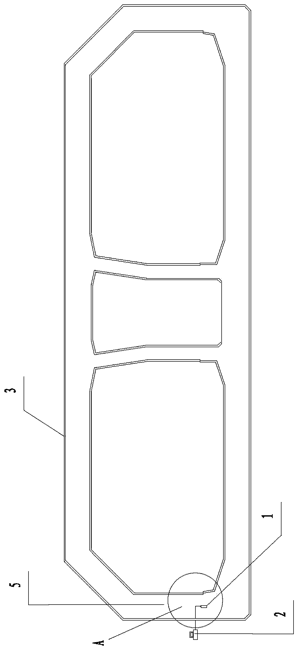
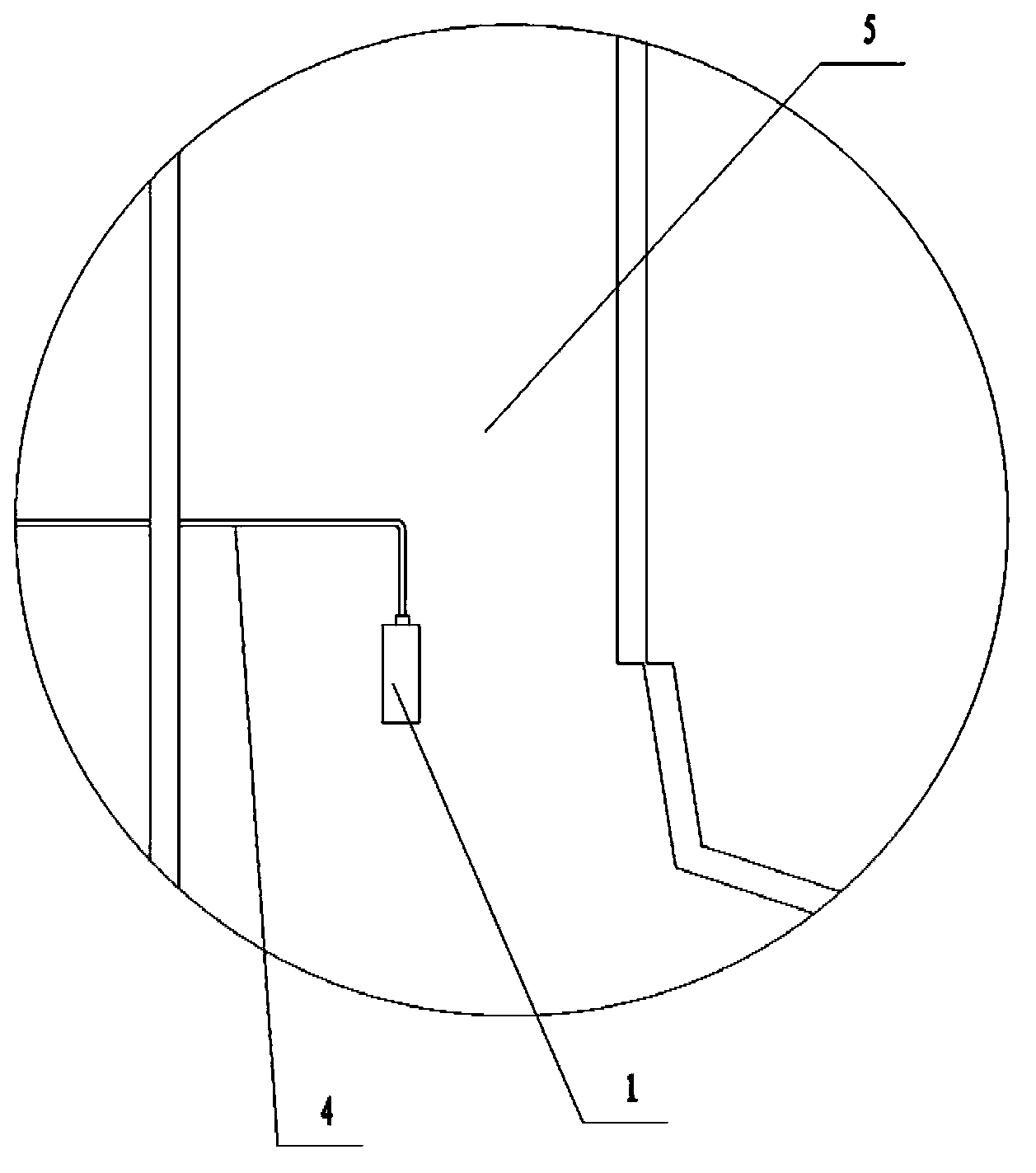
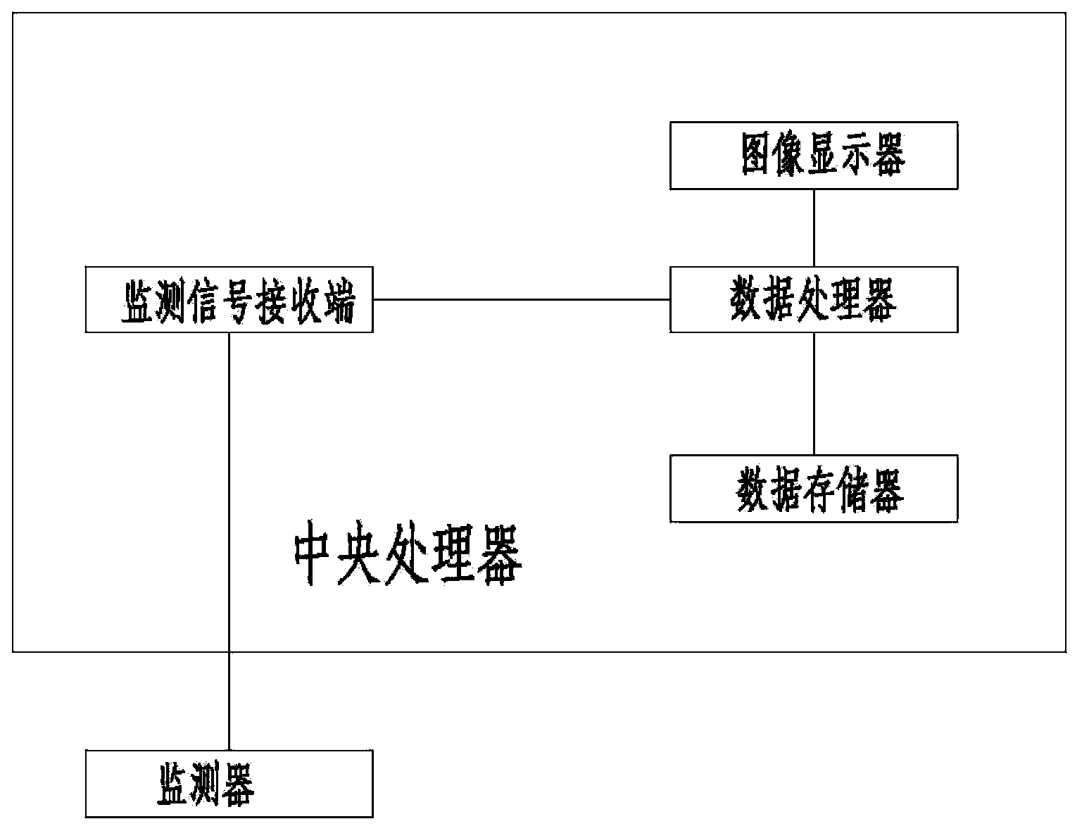
[0033] see figure 1 , figure 2 , image 3 As shown, the real-time monitoring system of the concrete setting state of the present invention, the real-time monitoring system includes a monitor 1 for real-time collection of concrete pressure values ​​and a central processing unit 2 connected thereto; the monitor is arranged in the pouring formwork 3 , and connect with the central processing unit outside the pouring formwork through the signal transmission cable 4 . The monitor is arranged in the side wall 5 of the pouring formwork; the monitor is arranged along the vertical centerline of the side wall. The monitors are set corresponding to the pre-marked monitoring points on the side wall. The monitoring point refers to the place 285cm away from the bottom surface on the vertical center line of the side wall of the pouring formwork. The monitor described in this embodiment is an earth pressure gauge; the earth pressure gauge is a vibrating earth pressure gauge with a disk sh...


PUM


Abstract

The invention relates to a real-time monitoring system and a real-time monitoring method of a condensing state of concrete and in particular relates to the real-time monitoring system used for determining the condensing time of the concrete according to change of a collected pressure value of a monitoring point location in a pouring process of the concrete. The real-time monitoring system comprises a monitor and a central processing unit connected with the monitor, wherein the monitor is arranged in a pouring template and connected with the central processing unit outside the pouring template by virtue of a signal transmission cable. By adopting the design of the monitor, the pressure value of the monitoring point location can be synchronously collected in real time. In addition, the monitor is small, exquisite and convenient and simple in setting and does not have effect on the structure of the concrete. By utilizing the real-time monitoring system, the measurement step is simplified, the construction process is accelerated, the construction cost is saved, and the work efficiency is improved.

Description

technical field [0001] The present invention relates to a real-time monitoring system and real-time monitoring method for the setting state of concrete, in particular to a real-time monitoring system and a real-time monitoring system for measuring the setting time of concrete by collecting and monitoring point pressure value changes during the concrete pouring process. monitoring method. Background technique [0002] At present, in the concrete pouring construction of the subsea tunnel, in order to facilitate the vibration of the pouring formwork, there are full-length gaps with a width of 10.85m and 3.85m respectively on the upper part of the bottom plate located in the driving corridor and the middle pipe gallery. If the side wall of the pouring formwork If the concrete on the bottom and bottom slab has not reached the initial setting state and the side wall concrete is continuously poured, the bottom slab concrete will easily rise from the gap due to the pressure differen...

Claims


Application Information

Patent Timeline
Patent Type & Authority Applications(China)
IPC IPC(8): G01N33/38
Inventor 林鸣翟世鸿屠柳青刘可心李进辉焦运攀杨永宏徐文冰查进伍绍博张明雷
Owner CCCC WUHAN HARBOR ENG DESIGN & RES
Why Eureka
Try Eureka