Pot
The technology of a pot body and a columnar body is applied to a pot. It can solve the problems of unfavorable Chinese food cooking, uneven temperature, sticky bottom of the pot, etc., and achieve the effect of easy cleaning, uniform temperature and enlarged heating area
- Summary
- Abstract
- Description
- Claims
- Application Information
AI Technical Summary
Problems solved by technology
Method used
Image

Examples
Embodiment 1
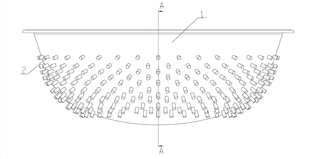
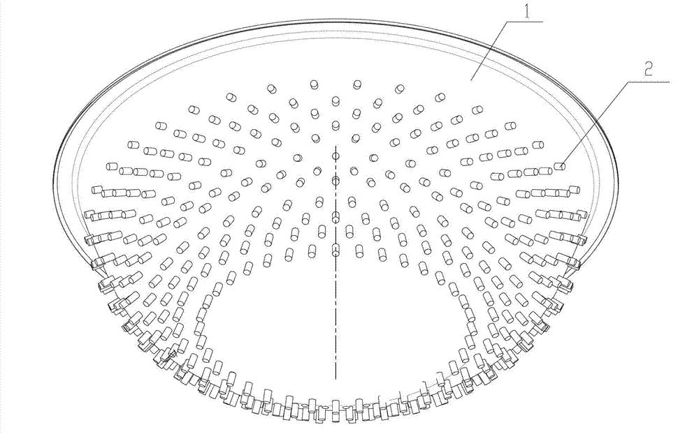
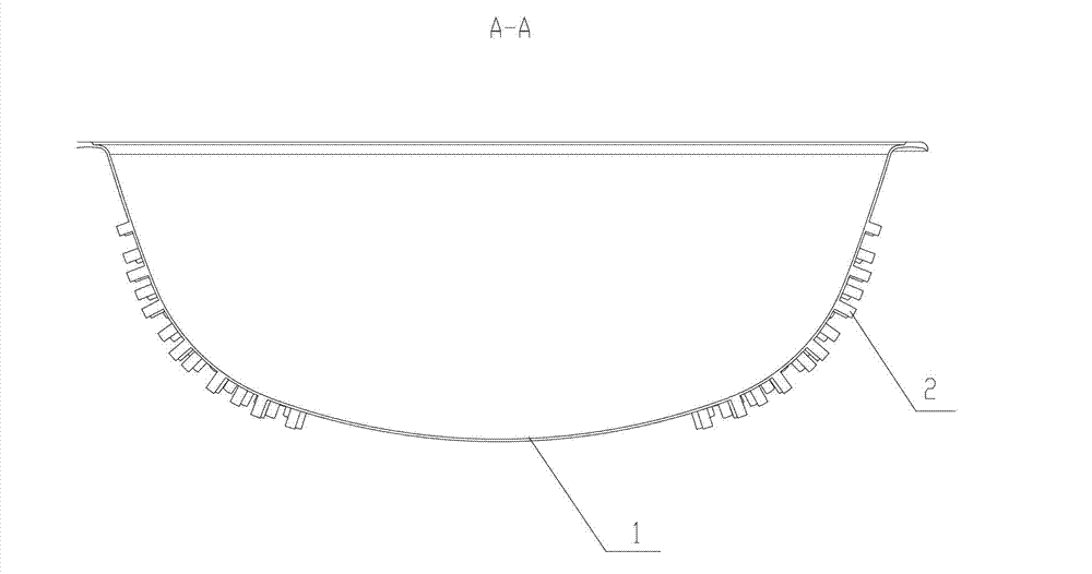
[0033] Such as Figure 1 to Figure 3 As shown, the pot according to the present invention is a metal pointed bottom pot such as an iron pot, an aluminum pot or a stainless steel pot, and includes a pot body 1, which is roughly hemispherical.
[0034] The side of the outer wall of the pot body 1 is provided with several outwardly protruding heat-absorbing protrusions 2, and the bottom of the pot body 1 does not have a heat-absorbing protrusion 2, which is a smooth surface, and the heat-absorbing protrusion 2 is a metal material, which is compatible with the pot. The material of the body 1 is the same, it can be integrally formed with the pot body 1 by casting, and can also be installed on the outer wall of the pot body 1 by welding, which is easy to process, and the heat conduction speed between the body 1 and the pot body 1 is fast.
[0035] The heat-absorbing protrusion 2 can adopt a semicircular or square protrusion or boss structure. In this embodiment, in order to improve ...
Embodiment 2
[0044] Such as Figure 5 As shown, the difference from Embodiment 1 is that several columnar heat-absorbing protrusions 2 protruding outward are provided on the side and bottom of the outer wall of the pot body 1 . Since the bottom of the pot body 1 is in direct contact with the flame, the temperature is high, so the height of the columnar heat-absorbing protrusions 2 arranged at the bottom of the pot body 1 is relatively short, about 5-10mm, and the higher the height, the higher the height of the columnar heat-absorbing protrusions 2 The height is relatively high, about 5-40mm.
[0045] In this way, while the heat absorbed by the bottom of the pot body 1 is increased, the heat absorbed by the bottom of the pot will not be too high, so that the bottom of the pot will become sticky.
Embodiment 3
[0047] Such as Figure 6As shown, the difference from Embodiments 1 and 2 is that an annular metal plate 4 is arranged around the pot body 1 on the side of the pot body 1, and the metal plate 4 can also be arranged in pieces on the outside of the pot body 1. The position of the bottom of the pot body 1 is not provided with a metal plate 4, and an interlayer 5 is formed between the metal plate 4 and the outer wall of the pot body 1, wherein part or all of the two ends of the columnar heat-absorbing protrusions 2 are welded and fixed to the pot body 1 and the pot body 1 respectively. On the metal plate 4 , the material of the metal plate 4 is consistent with that of the heat-absorbing protrusion 2 . The heat-absorbing protrusion 2 can be cast integrally with the pot body 1, and the other end is welded and fixed with the metal plate 4 again.
[0048] When the high-temperature flue gas rises from the bottom of the pot body 1 to both sides, the flue gas will rise along the interla...
PUM
| Property | Measurement | Unit |
|---|---|---|
| Height | aaaaa | aaaaa |
Abstract
Description
Claims
Application Information
 - Generate Ideas
- Intellectual Property
- Life Sciences
- Materials
- Tech Scout
- Unparalleled Data Quality
- Higher Quality Content
- 60% Fewer Hallucinations
Browse by: Latest US Patents, China's latest patents, Technical Efficacy Thesaurus, Application Domain, Technology Topic, Popular Technical Reports.
© 2025 PatSnap. All rights reserved.Legal|Privacy policy|Modern Slavery Act Transparency Statement|Sitemap|About US| Contact US: help@patsnap.com