Non-wear laminated solid-liquid separation device

A solid-liquid separation, lamination technology, applied in the direction of filtration separation, separation method, fixed filter element filter, etc., can solve the problem of wear of moving filter and screw shaft, etc., to prolong the service life, reduce the pitch, and achieve the effect of treatment Good results

Inactive Publication Date: 2014-07-16
KANGTAI JIANGSU ENVIRONMENTAL PROTECTION LTD BY SHARE LTD
View PDF4 Cites 6 Cited by
  • Summary
  • Abstract
  • Description
  • Claims
  • Application Information

AI Technical Summary

Problems solved by technology

[0007] The purpose of the present invention is to provide a wear-free laminated solid-liquid separation device to solve the problem of wear and tear on the moving filter and the screw shaft in the laminated solid-liquid separation equipment. No contact movement with the screw shaft, no hard contact wear, longer service life

Method used


Image

  • Non-wear laminated solid-liquid separation device
  • Non-wear laminated solid-liquid separation device
  • Non-wear laminated solid-liquid separation device

Examples


Embodiment 1

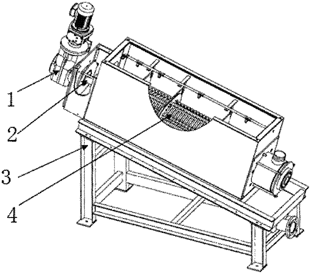
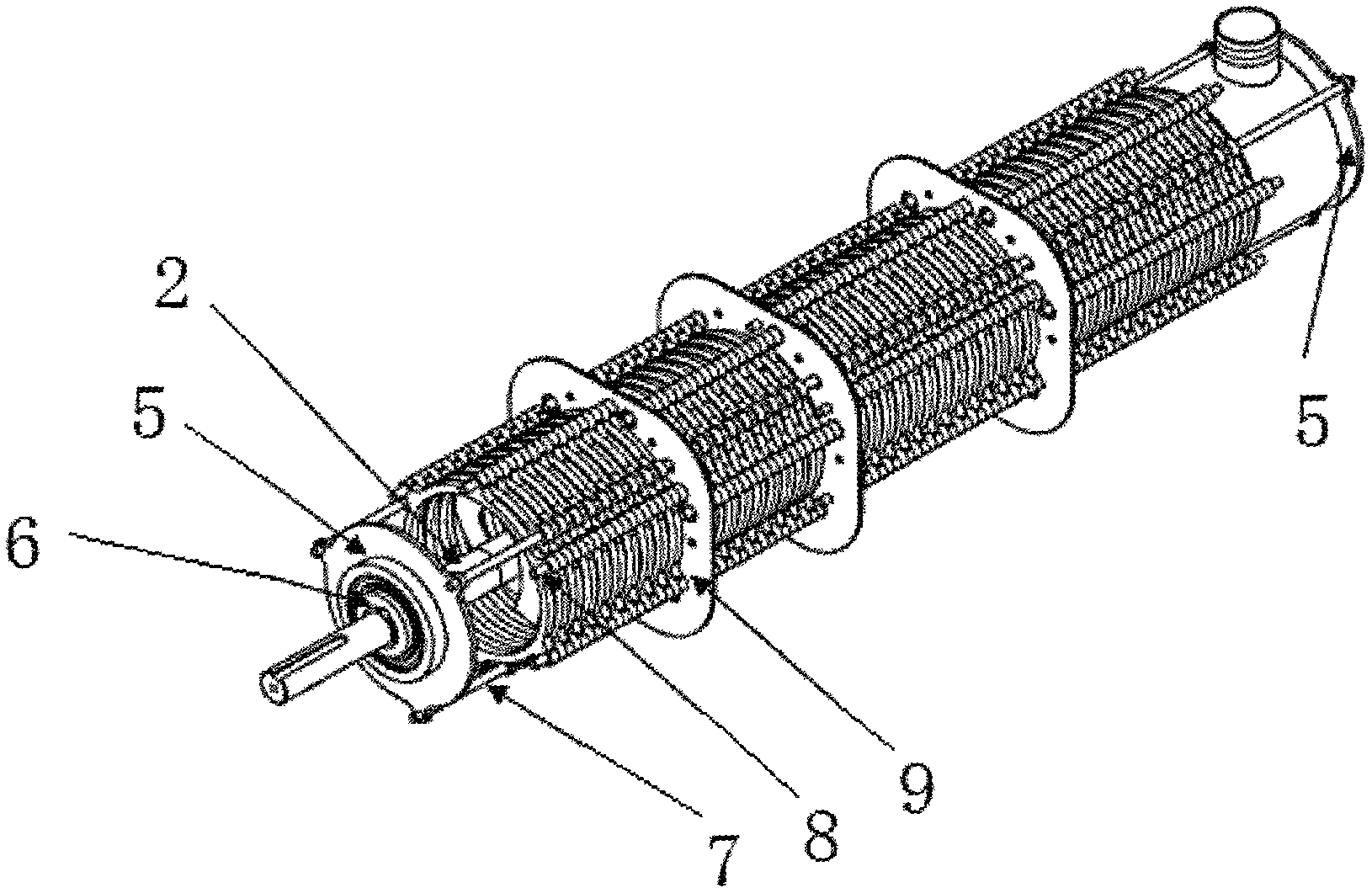
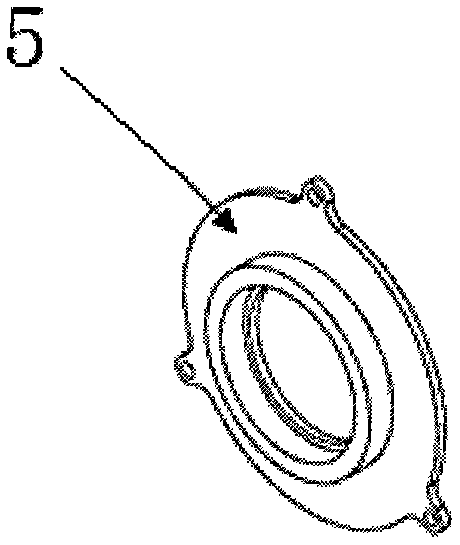
[0024] Such as Figure 1 ~ Figure 6 As shown, the wear-free laminated solid-liquid separation device includes a base 3, a screw shaft with spiral blades 2, a reduction motor 1 that drives the screw shaft to rotate, and a filter pack 4 nested around the screw shaft. The filter group 4 is composed of a number of fixed plates 10 and moving plates 11 arranged at intervals in the axial direction, and a fixed plate support shaft 8, a fixed plate support plate 9, and a moving plate support shaft 7, which are connected to support them. 4Fixed on the base 3 by the stator support plate 9. There are 6 ears around each stator 10, and each ear is provided with a positioning hole for the stator support shaft 8 to pass through, and all the stators 10 pass through. The stator support shaft 8 that penetrates them is connected to the stator support plate 9. Each of the moving plates 11 has 3 ears around it, and each ear has a positioning hole for the moving plate support shaft 7 to pass through....


PUM


Abstract

The invention discloses a non-wear laminated solid-liquid separation device belonging to the technical field of sewage treatment equipment. A filter disk assembly of the device is formed by a plurality of stator plates and rotor plates, stator plate support shafts, stator plate support plates and rotor plate support shafts, wherein the plurality of stator plates and rotor plates are crossly arranged in the axial direction at intervals; the stator plate support shafts, the stator plate support plates and the rotor plate support shafts are connecting and supporting the stator plates and the rotor plates; the filter disk assembly is fixed on a base through the stator plate support plates; one rotor plate is arranged between each two adjacent stator plates; a rotor plate drive plate is arranged on an eccentric gear; the eccentric gear is connected with a screw shaft through a key. The rotor plates and the screw shaft in the device disclosed by the invention are in contactless motion and free of direct abrasion, so that the service life of each rotor plate is prolonged, and the maintenance cost is saved; the screw pitch of a screw shaft blade is not limited when the rotor plate support shafts is driven by a cam device to drive the rotor plates to shake around the center of the screw shaft, and the screw pitch can be greatly shortened so as to improve the compression ratio and reduce the moisture content of a mud cake.

Description

Technical field [0001] The invention belongs to the technical field of sewage treatment equipment, and specifically relates to a wear-free laminated solid-liquid separation device. Background technique [0002] At present, in the treatment and treatment of sewage, the selection and design of sewage dewatering machine is extremely critical. Traditional sewage dewatering machines include plate and frame filter presses, belt filters, centrifugal filters, etc. However, these dewatering machines have an obvious disadvantage that their filter cloth and filter belts are prone to blockage or damage, or energy consumption. The high cost affects the final effect of sewage treatment. [0003] In order to improve the effect of sewage sludge treatment, many enterprises and their technical personnel have carried out a lot of research on the improvement of sewage dewatering equipment, and developed a stacked screw sludge dewatering machine. The design concept is composed of a screw shaft and mul...

Claims


Application Information

Patent Timeline
IPC IPC(8): B01D29/46B01D29/62
Inventor 王飞袁飞花成巍
Owner KANGTAI JIANGSU ENVIRONMENTAL PROTECTION LTD BY SHARE LTD
Why Eureka
Try Eureka