Air purification equipment and air purification device comprising air purification equipment

An air purification equipment and air technology, which is applied in the field of air purification equipment and air purification devices, can solve the problems of low adsorption efficiency of charged particles, low single filtration efficiency, small contact surface area, etc., to increase the probability of capture, Improves the chance of adsorption and increases the chance of collision

Inactive Publication Date: 2014-07-16
吴镇海 +2
View PDF6 Cites 4 Cited by
  • Summary
  • Abstract
  • Description
  • Claims
  • Application Information

AI Technical Summary

Problems solved by technology

In the air purification equipment, the particles in the airflow are charged by a corona discharge device or a radiation ionization device to achieve the purpose of adsorbing charged particles. However, for particles with high specific re

Method used


Image

  • Air purification equipment and air purification device comprising air purification equipment
  • Air purification equipment and air purification device comprising air purification equipment
  • Air purification equipment and air purification device comprising air purification equipment

Examples


Embodiment 1

[0040] This embodiment is further deepened on the structural basis of the above-mentioned air purification equipment. It is known that each set of conductive material parts comprises two layers of conductive material with a dust collecting plate between the two layers of conductive material. Preferably, a dust collecting plate is provided between each group of conductive material parts.

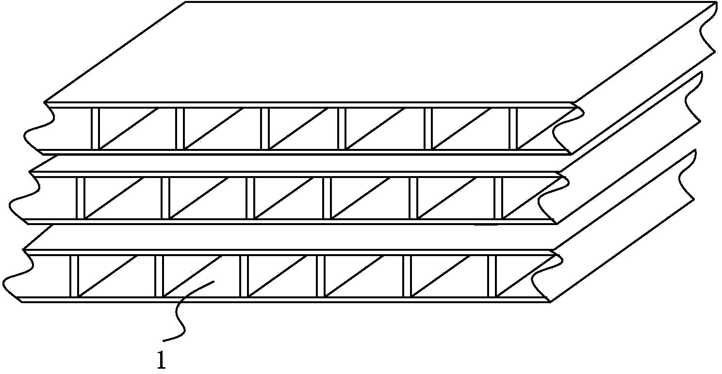
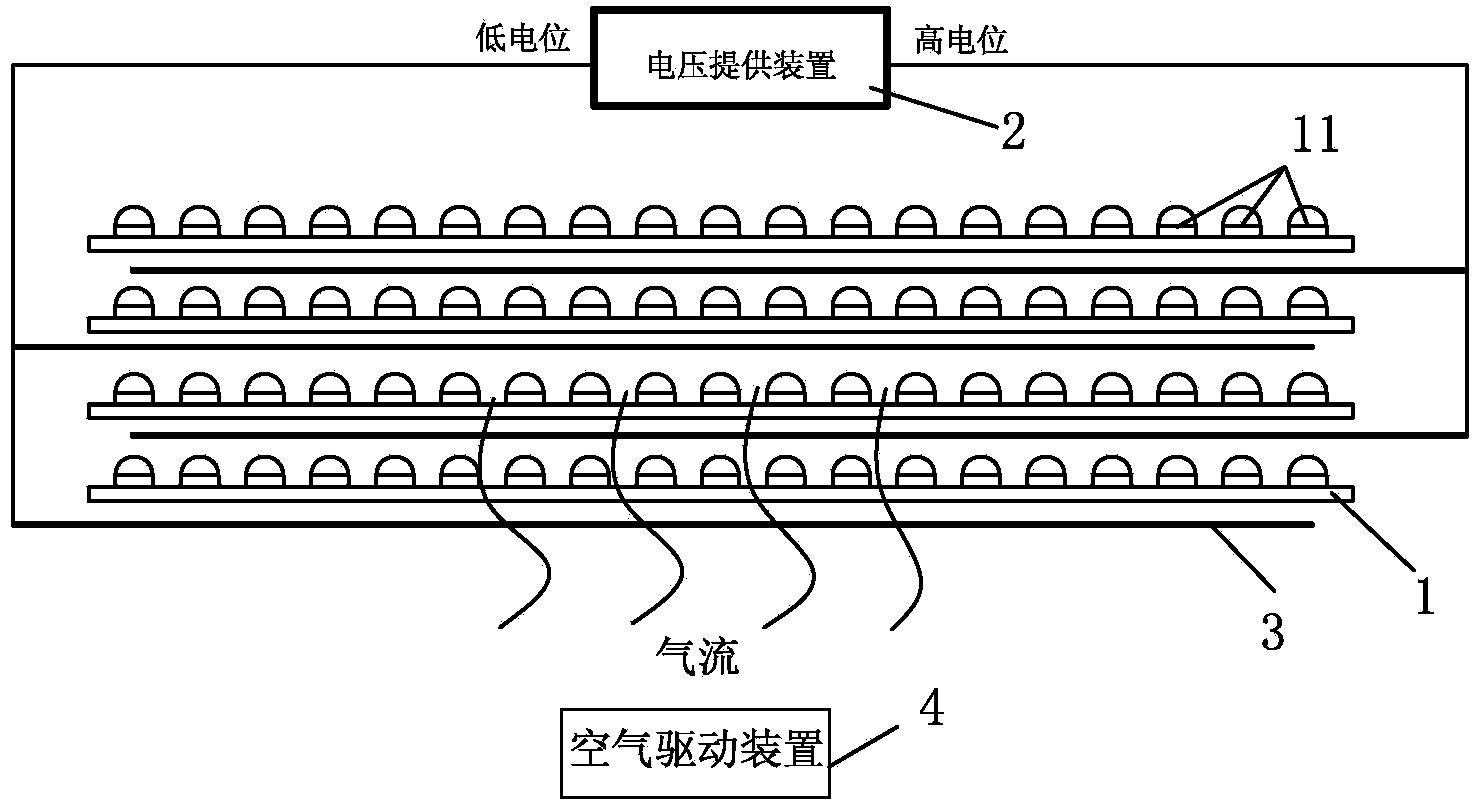
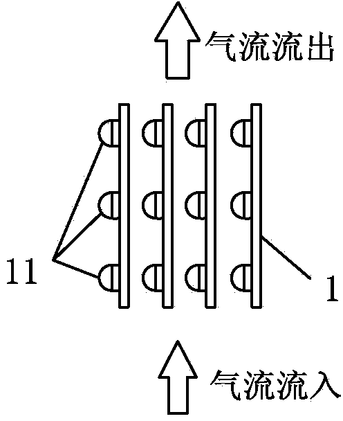
[0041] Such as Figure 4 As shown, the layers of conductive material and the dust collecting plate 1 are alternately arranged. The polarity between adjacent layers of conductive material of a dust collection plate is reversed. When the material of the dust collecting plate contains electret material, a semi-permanent electret electric field is formed inside under the action of an external electric field. When the voltage supply device 2 is turned on, a uniform electric field is formed between adjacent conductive material layers, and at the same time, the electric field polarizes the electr...

Embodiment 2

[0045] The difference between this embodiment and the first embodiment lies in that at least two dust collecting plates are arranged between each group of conductive material parts. The material of the dust collecting plate contains electret material, and a semi-permanent electret electric field is formed inside under the action of an external electric field. A plurality of dust-collecting plates 1 are stacked together to form a filter device, and the overall dust-collecting area is greatly increased through multiple sets of stacked arrays of dust-collecting plates. Due to the existence of the electret, there is no particularly large loss of efficiency if the dust collecting plates are arranged at intervals of one sheet or at intervals of multiple sheets. In the experiment, the difference in purification efficiency loss between three electrodes and one electrode at intervals is about 5%. This solution can reduce the cost of implementation by reducing the number of electrode d...

Embodiment 3

[0047] This embodiment is improved on the basis of Embodiment 1 or Embodiment 2. Such as Figure 4 As shown, there is an air gap 5 between the conductive material layer and the dust collecting plate in this embodiment, that is, there is no contact between the conductive material layer and the dust collecting plate. The air gap between the conductive material layer and the dust collecting plate is realized by the bracket 6 . The bracket 5 is arranged between the two dust-collecting plates 1, and the conductive material layer and the dust-collecting plates are overhead, so that an air gap 5 is formed between the two brackets and the dust-collecting plates. Figure 4 The support is "H" type, two support legs support its two dust collecting plates 1, and the upper and lower surfaces of the connecting plate in the middle are respectively provided with a conductive material layer, and the two conductive material layers are conducted. Or just a layer of conductive material. Among ...


PUM


Abstract

The invention discloses air purification equipment and an air purification device. The air purification equipment comprises dust collection plates, a voltage supply device, conductive material parts arranged on the surfaces of the dust collection plates, and an air driving device, wherein a protrusion array for interfering airflow flowing through the surfaces of the dust collection plates to generate local turbulence is arranged on the surfaces of the dust collection plates; each group of conductive material parts comprises two conductive material layers; at least one dust collection plate is arranged between the two conductive material layers; air gaps are formed between the conductive material layers and the dust collection plates; the voltage supply device applies high potential and low potential to the two conductive material layers of each group of conductive material parts respectively, so that the dust collection plates between the two conductive material layers adsorb charged particles of airflow which flows through the surfaces of the dust collection plates. The airflow which flows through the dust collection plates is interfered by the protrusion array to generate local turbulence, and silicate and other particles with high specific resistance are violently collided or are collided with the protrusion array to be retained on the surface of the protrusion array along pressure layering of the airflow, so that the passing rate of the particles is reduced.

Description

technical field [0001] The present invention relates to air cleaning equipment and an air cleaning device including the air cleaning equipment. Background technique [0002] Existing air cleaners have achieved electrostatic dust removal. For example, the patent No. ZL00806175.0, the patent of the invention titled air purification equipment, uses plastic array channels, conductive materials arranged on the surface of the array channels, high and low potential output devices interlaced with conductive materials, and devices that provide wind flow. Through the air purification equipment, the charged particles and neutral particles passing through the plastic array channel can be effectively reduced. In this air purification equipment, the particles in the airflow are charged by a corona discharge device or a radiation ionization device to achieve the purpose of adsorbing charged particles. However, for particles with high specific resistance, such as silicate particles, they c...

Claims


Application Information

Patent Timeline
IPC IPC(8): B01D50/00
Inventor 郎欢标刘广胜孙茂华
Owner 吴镇海
Why Eureka
Try Eureka