
Front cam type abrasive belt rectification mechanism and rectification method of broadband sander

A wide-band sander, cam-type technology, applied in belt grinders, feeding devices, automatic control devices, etc., can solve problems such as deviation, inconvenience, and insecurity, and achieve time-saving and labor-saving operation, easy maintenance, and structure. simple effect

Active Publication Date: 2016-07-06
HANGZHOU XIANGSHENG ABRASIVE MACHINE MFG
View PDF7 Cites 2 Cited by
  • Summary
  • Abstract
  • Description
  • Claims
  • Application Information

AI Technical Summary

Problems solved by technology

[0002] 1. Generally, the wide-band sanding machine inevitably has different sizes and sizes of the abrasive belts used, so when it is installed on the machine and used, it will appear to deviate to the smaller end. At this time, it is necessary to have a The mechanism is used to correct the initial error of the new abrasive belt. Ordinary broadband sanders install this mechanism on one side of the main motor. The mechanism is also a screw connected between the frame and the swing head cylinder, using a handwheel or nut Adjusting the telescopic length to adjust the initial position of the abrasive belt requires the use of a wrench or other tools, and the adjustment position is not in the normal operating position, which is inconvenient and has potential safety hazards
[0003] 2. The new abrasive belt can be used normally after the initial positioning is completed. However, due to the uneven wear of the abrasive belt and the elongation of the cloth base during use, the trajectory of the abrasive belt will also change. At this time, timely adjustment is required. For the angle between the tension roller and the contact roller of the sanding head, the ordinary correction mechanism is installed on the side of the main motor, which is inconvenient and unsafe

Method used


Image

  • Front cam type abrasive belt rectification mechanism and rectification method of broadband sander
  • Front cam type abrasive belt rectification mechanism and rectification method of broadband sander
  • Front cam type abrasive belt rectification mechanism and rectification method of broadband sander

Examples


Embodiment 2

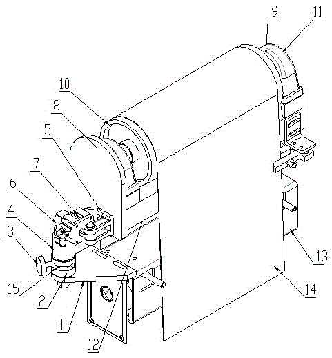
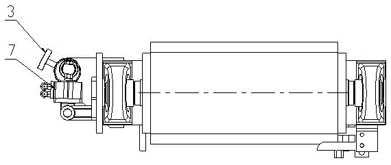
[0017] Embodiment 2: On the basis of Embodiment 1, a method for correcting the deviation of the front cam type abrasive belt of a broadband sander, when it is necessary to adjust the angle between the tension roller and the headstock (contact roller), loosen the lock Screw 3 and turn the locking screw 3, the locking screw 3 flexibly moves in the chute 15 and drives the eccentric shaft sleeve 4 in the column sleeve 2 to rotate, the eccentric shaft sleeve 4 drives the telescopic column 6 to perform cam eccentric movement, and at the same time the telescopic column 6 drives the swing head cylinder 7 to drive the upper beam 12 through the upper beam connection seat 8 to make a slight angular deviation, and then tighten the locking screw 3 after deflecting to a suitable position, the operation is very convenient and fast.


PUM


Abstract

The invention relates to a front-arranged cam type sanding belt deviation correction mechanism for a wide belt sanding machine. The front-arranged cam type sanding belt deviation correction mechanism comprises an upper beam tensioning roller of a machine head. An oscillating air cylinder is arranged on the side surface of the upper beam tensioning roller through a hinged mechanism. A vertical column sleeve is arranged on the side surface of a fixing beam of a sanding head, and an eccentric shaft sleeve is arranged above the vertical column sleeve. The concentric shaft end at the lower portion of the eccentric shaft sleeve is arranged in the vertical column sleeve, and a telescopic vertical column is arranged at the eccentric shaft end of the upper portion of the eccentric shaft sleeve. The top of the telescopic vertical column is connected with the oscillating air cylinder. The front-arranged cam type sanding belt deviation correction mechanism for the wide belt sanding machine is simple in structure, low in cost and convenient to operate and control, deviation and fixation of the eccentric shaft sleeve can be controlled through a locking screw, and operation saves the time and the labor greatly.

Description

technical field [0001] The invention relates to a wide-band sander for grinding and deburring workpieces. The cam-type abrasive belt deviation correction mechanism at the front of the wide-band sander by adjusting the angle between the tension roller and the contact roller belongs to the sanding machine in the deburring machine. It relates to the technical field of a deviation-correcting control mechanism. Background technique [0002] 1. Generally, the wide-band sanding machine inevitably has different sizes and sizes of the abrasive belts used, so when it is installed on the machine and used, it will appear to deviate to the smaller end. At this time, it is necessary to have a The mechanism is used to correct the initial error of the new abrasive belt. Ordinary broadband sanders install this mechanism on one side of the main motor. The mechanism is also a screw connected between the frame and the swing head cylinder, using a handwheel or nut To adjust the telescopic lengt...

Claims


Application Information

Patent Timeline
Patent Type & Authority Patents(China)
IPC IPC(8): B23Q15/14B24B21/20
CPCB24B21/20
Inventor 陈勇奇
Owner HANGZHOU XIANGSHENG ABRASIVE MACHINE MFG
Learn More