Sliding arc ignition device

An ignition device and sliding arc technology, which is applied in the direction of rocket engine devices, jet propulsion devices, gas turbine devices, etc., can solve problems that have not yet reached mature application, achieve the effects of enhanced combustion, reduced ignition delay time, and reduced processing difficulty

Active Publication Date: 2014-07-16
CHINA ACAD OF AEROSPACE AERODYNAMICS
View PDF6 Cites 19 Cited by
  • Summary
  • Abstract
  • Description
  • Claims
  • Application Information

AI Technical Summary

Problems solved by technology

But at the same time, it is also pointed out that non-equilibrium plasma combustion enhancement technology is still

Method used


Image

  • Sliding arc ignition device
  • Sliding arc ignition device
  • Sliding arc ignition device

Examples


Embodiment 1

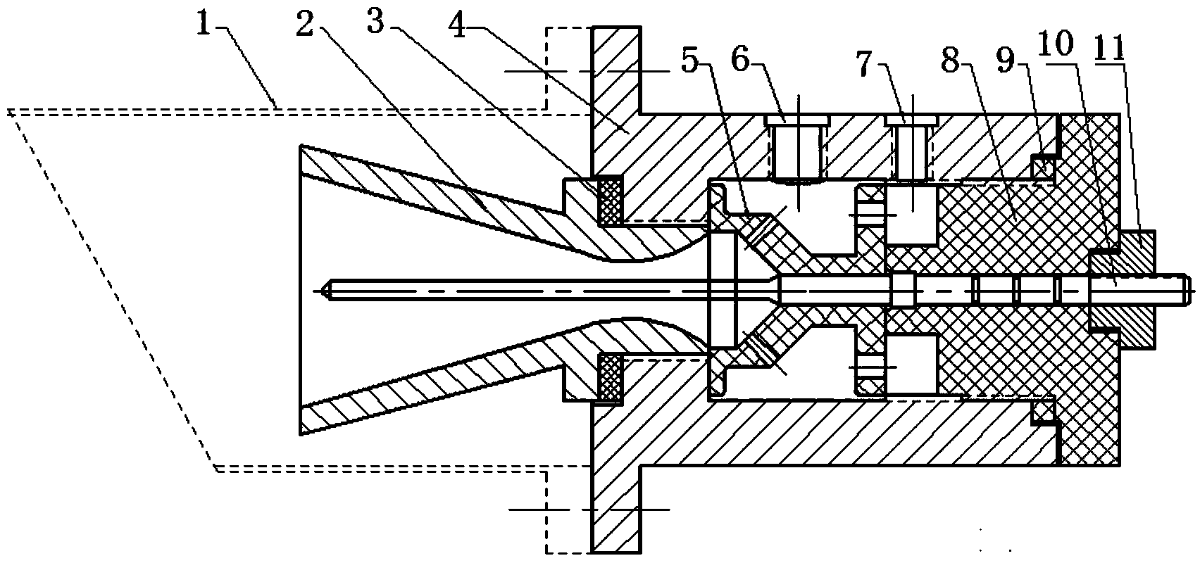
[0029] Such as figure 1 As shown, the sliding arc ignition device of the present invention includes a contraction-expansion type Laval nozzle 2, a casing 4, an airflow baffle 5, an electrode mounting seat 8, a high-voltage anode 10 and a lock nut 11, and the contraction-expansion type Laval nozzle The Val nozzle 2 and the electrode mounting seat 8 are fixed on the casing 4 through threads, and the oil vapor fuel inlet 6 and the auxiliary gas inlet 7 are arranged on the casing 4, and the airflow baffle 5 is clamped between the casing 4 and the electrode mounting seat 8 , the high-voltage anode 10 is inserted into the center hole of the electrode mounting base 8, and the end of the high-voltage anode 10 has an external thread for connecting the lock nut 11. The high-voltage anode 10 is fixed and locked on the electrode mounting base 8 by bonding the sealant and the lock nut 11

[0030] The flame connection pipe 1 is installed on the engine or equipment casing support to form a ...

Embodiment 2

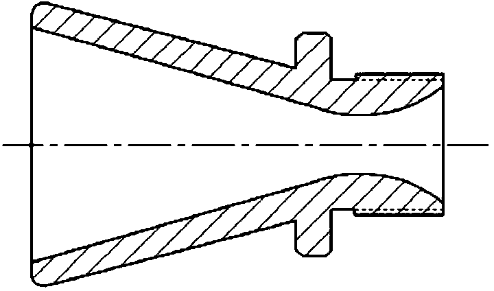
[0040] According to different ignition flame flow modes, this embodiment adopts contraction-expansion type Laval oblique nozzle, such as Figure 9 Shown, to adapt to ignition requirements, all the other parts are identical with embodiment 1.

Embodiment 3

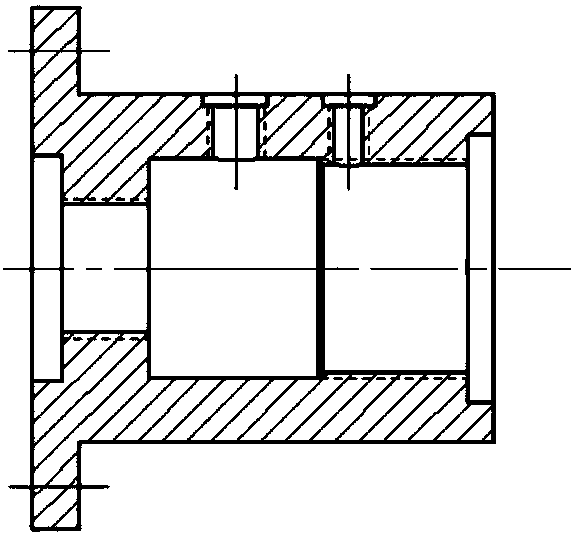
[0042] This embodiment adopts another kind of airflow baffle, such as Figure 10 Shown, all the other parts are identical with embodiment 1.

[0043] As can be seen from the above description, the above-mentioned embodiments of the present invention have achieved the following technical effects: by introducing the auxiliary gas source of the sliding arc, a sliding arc of a certain energy intensity is generated at the central high-voltage anode and the inner wall of the Laval nozzle, The inlet introduces combustible gas or a mixture of oil and gas with a certain ratio. When it passes through the arc area, it ignites and burns. The flame sprays out of the nozzle and is separated from the nozzle by the blowing of the airflow. There is a certain distance between the defire zone, and the ignition device is at a low temperature. Under the action of the arc, the fuel can be pre-catalyzed and then sprayed into the combustion chamber to play a role in continuous combustion. Since the ...


PUM

PropertyMeasurementUnit
Diameteraaaaaaaaaa
Diameteraaaaaaaaaa

Abstract

The invention discloses a sliding arc ignition device. The sliding arc ignition device comprises a contract-expansion type Laval nozzle, an outer shell, an air flow baffle, an electrode installation seat, a high-voltage anode and a locknut, wherein the contract-expansion type Laval nozzle and the electrode installation seat are fixed to the outer shell through threads, a hole is formed in a radial position of the outer shell, an air inlet connector is installed in the hole, the air flow baffle is clamped between the outer shell and the electrode installation seat, and the high-voltage anode is inserted into a central hole of the electrode installation seat, is stuck through sealants, is fixed through the locknut and is locked on the electrode installation seat. The sliding arc ignition device adopts an independent fuel inlet, the fuel supply can be increased after ignition succeeds, the fuel is catalyzed in a plasma region, and the functions of shortening ignition delay time and intensifying combustion are achieved. According to the design concept, a shell body serves as the installation base, machining difficulty is lowered, and when air flow baffles with different purposes are used, the air flow baffles can be placed in the outer shell without constraints, and assembling efficiency is improved.

Description

technical field [0001] The invention relates to the field of aerospace engines, in particular to a sliding arc ignition device for generating atmospheric pressure non-equilibrium plasma. Background technique [0002] According to the particle temperature of plasma, plasma is divided into high-temperature plasma and low-temperature plasma. Through control means and scientific methods, most of the plasmas that can be produced and widely used in industrial and agricultural production are low-temperature plasmas. According to the thermodynamic equilibrium characteristics of the arc region, low temperature plasma can be divided into hot plasma and cold plasma. Cold plasma is a kind of non-thermal equilibrium plasma, the temperature of electrons is much higher than that of ions, and the temperature of ions is much higher than that of neutral particles. Judging from the existing literature, the methods of generating non-equilibrium plasma mainly include dielectric barrier discharg...

Claims


Application Information

Patent Timeline
IPC IPC(8): F02K9/95F02C7/266
Inventor 郭孝国赵学军王宏亮陈峰王铁进
Owner CHINA ACAD OF AEROSPACE AERODYNAMICS
Why Eureka
Try Eureka