A Plasma-Based Orbital Sliding Arc Actuator

A plasma and exciter technology, which is applied in the direction of plasma, machine/engine, electrical components, etc., can solve the problems of plasma sliding arc and air in the outer channel, contact time of atomized fuel is short, discharge area is limited, etc. , to achieve the effect of widening the flameout boundary, reducing combustion pollutant emissions, and reducing pollutant emissions

Active Publication Date: 2020-07-31
AIR FORCE UNIV PLA
View PDF3 Cites 0 Cited by
  • Summary
  • Abstract
  • Description
  • Claims
  • Application Information

AI Technical Summary

Problems solved by technology

[0005] For example, the transient plasma igniter disclosed in the Chinese utility model patent application number 201320339282.9 for the combustion chamber of an internal combustion engine, and the air swirl plasma igniter disclosed in the Chinese invention patent application number 201310084697.0, Both of these igniters adopt the idea of ​​plasma ignition, which improves the ignition characteristics to a certain extent, but still faces the problems of complex discharge structure and limited discharge area.
[0006] In addition, as disclosed in the Chinese invention patent application document with the application number 201711344497.9, the rotary sliding arc plasma fuel cracking head of the aero-engine combustor, this scheme is to set the discharge area of ​​the fuel cracking head in the small Venturi of the inner channel between the large venturi tube and the outer channel, but the plasma sliding arc has more contact with the air in the outer channel, and the contact time with the atomized fuel is shorter, which fails to maximize the cracking effect of the sliding arc plasma on the fuel

Method used


Image

  • A Plasma-Based Orbital Sliding Arc Actuator
  • A Plasma-Based Orbital Sliding Arc Actuator
  • A Plasma-Based Orbital Sliding Arc Actuator

Examples


Embodiment 1

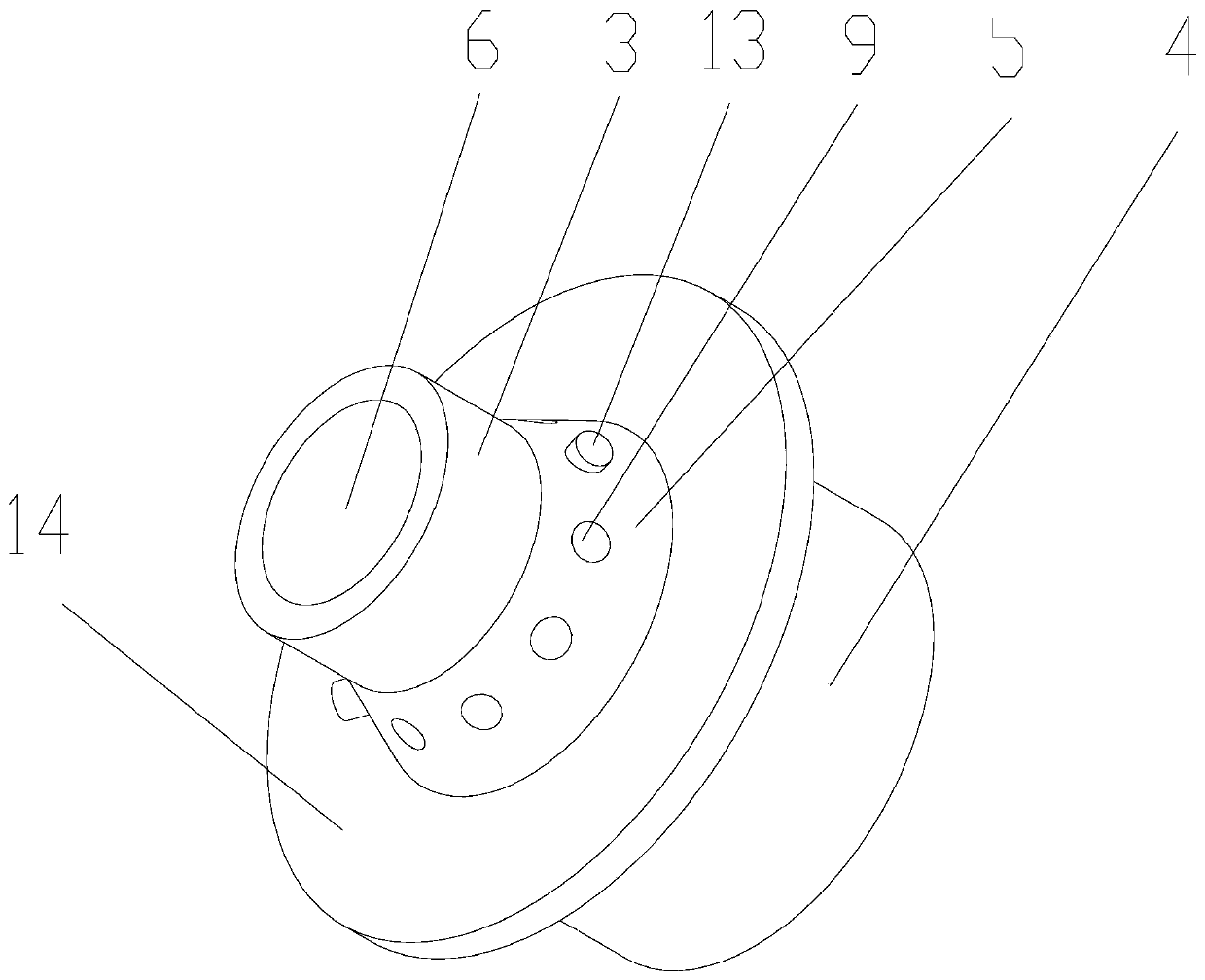
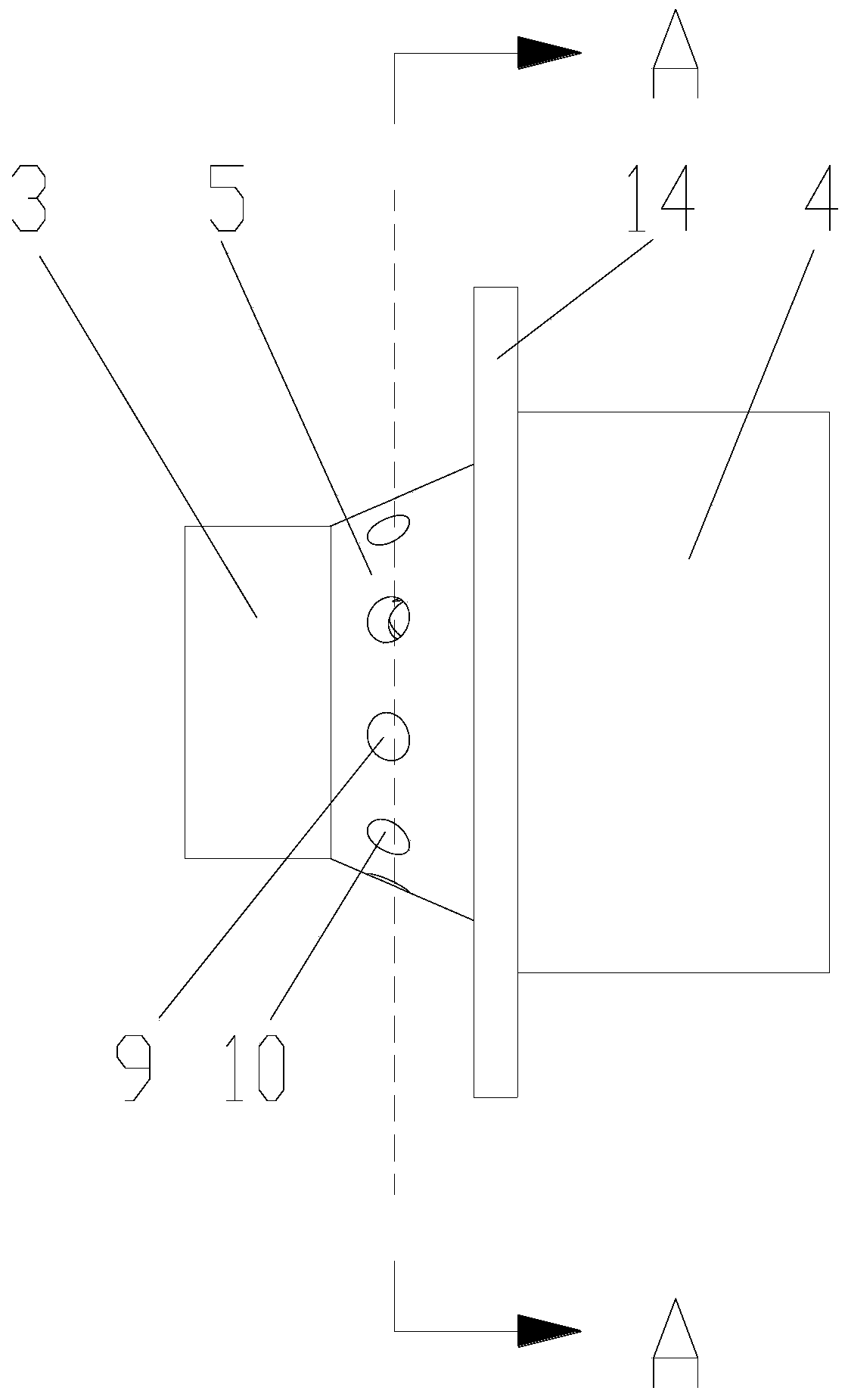
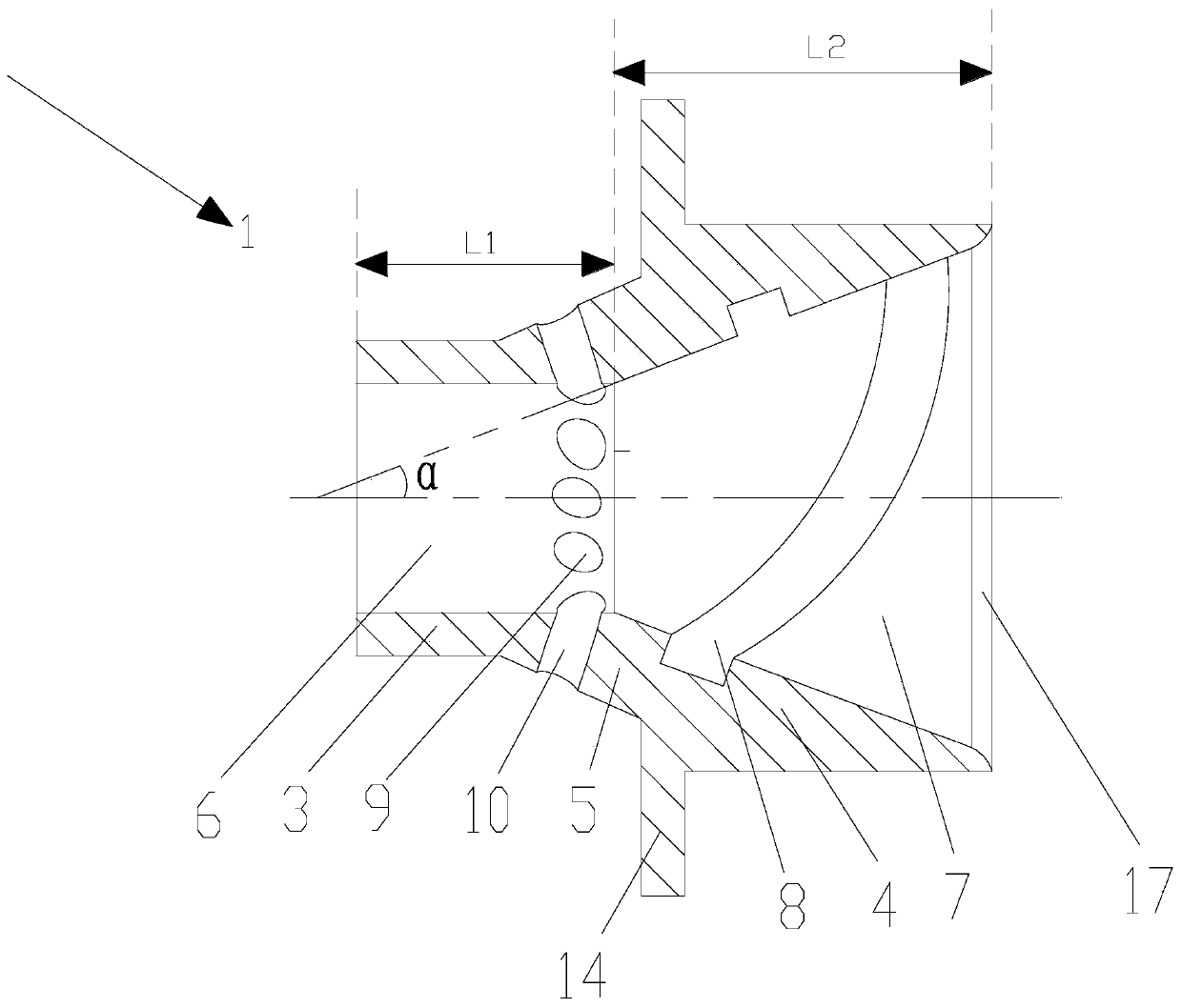
[0049] Such as figure 1 , figure 2 , image 3 with Image 6 As shown, a plasma-based orbital sliding arc exciter includes an exciter body 1 and two electrodes 2 with the same structure and used to generate arcs. The exciter body 1 includes first joints 3, The swirl joint 5 and the second joint 4, the first joint 3, the second joint 4 and the swirl joint 5 are integrally formed, and the axes of the first joint 3, the swirl joint 5, and the second joint 4 are uniform on the same straight line.

[0050] Such as figure 1 , image 3 , Figure 5 with Image 6 As shown, the interior of the first joint 3, the swirl joint 5 and the second joint 4 are all hollow structures, and the internal hollow structures of the three jointly form an inner channel, and the inner channel includes a swirl flow for connecting fuel nozzles. The channel 6 and the diffusion channel 7 used to connect the combustion chamber of the engine, the swirl channel 6 is a cylindrical channel, and the diffusi...

Embodiment 2

[0065] Such as Figure 10As shown, the difference between this embodiment and Embodiment 1 is that the cross-sectional shape of each of the electrode grooves 8 is square and the cross-sectional area of ​​one of the electrode grooves 8 is larger than the cross-sectional area of ​​the remaining electrode grooves 8. Each of said electrodes 2 is a rectangle 19 in cross-sectional shape, and the length of each said electrode 2 cross-section is equal to the width of its correspondingly installed electrode slot 8, and the width of each said electrode 2 cross-section is corresponding to its correspondingly installed electrode slot. 2 have the same depth, and the electrodes 2 are all arranged inside the electrode groove 8, so as to reduce the influence of air on the arc without affecting its discharge. The electrode 2 is matched with the inner side of the electrode groove 8 and the part of the electrode 2 in contact with the electrode groove 8 is adhered, and the outer end of the termin...

Embodiment 3

[0069] Such as Figure 11 As shown, the difference between this embodiment and Embodiment 1 is that the cross-sectional shape of each electrode slot 8 is square, equal in size, and identical in structure, and the electrodes 2 are disposed inside the electrode slot 8 by casting.

[0070] In this embodiment, the structures, connections and working principles of other parts are the same as those in Embodiment 1.


PUM


Abstract

The invention discloses a rail type sliding arc exciter based on plasma. The rail type sliding arc exciter based on the plasma comprises an exciter body and electrodes, wherein the number of the electrodes is at least two, and the electrodes are used for generating electric arcs; the exciter body comprises a first contact, a rotational flow section and a second connect, wherein the shape of the first contact and the shape of the second contact both are cylindrical, the shape of the rotational flow section is in a circular truncated cone shape, the first connect, the second connect and the rotational flow section are of an integrated forming structure, the axes of the first connect, the second connect and the rotational flow section are positioned on the same straight line, the small end ofthe rotational flow section is arranged at one end of the first connect, and the large end of the rotational flow section is arranged at one end of the second connect. According to the rail type sliding arc exciter, the structure is simple, the plasma is used for reinforcing combustion, the ignition boundary of an engine is expanded, the ignition success rate and the combustion efficiency of theengine are improved, and the rail type sliding arc exciter can be popularized and used.

Description

technical field [0001] The invention relates to the technical field of aerodynamic plasma ignition and combustion enhancement, in particular to a plasma-based orbital sliding arc exciter. Background technique [0002] With the continuous development and progress of aviation equipment, higher requirements are placed on the performance of the engine. At present, the aero-turbine engines used on aircraft basically use the head of the combustion chamber with a swirler, and at the same time use electric sparks for ignition. Insert the spark plug in the appropriate place in the low pressure recirculation area to ignite. This ignition method has many disadvantages: first, the ignition energy of the spark plug is relatively small, and the air pressure, oil-gas ratio, oxygen content and other conditions required for ignition are relatively harsh, which directly limits the ignition range of the engine and affects the performance of the engine; Ignition completely relies on the low-p...

Claims


Application Information

Patent Timeline
Patent Type & Authority Patents(China)
IPC IPC(8): F02C7/264H05H1/48
CPCF02C7/264H05H1/48
Inventor 于锦禄蒋永健李帅国陈朝蒋陆昀彭畅新王思博杨犇鑫谭新耀何立明
Owner AIR FORCE UNIV PLA
Why Eureka
Try Eureka