Multi-watt integral brake
What is Al technical title?
Al technical title is built by PatSnap Al team. It summarizes the technical point description of the patent document.
A brake and integral technology, which is applied in the direction of mechanically driven drum brakes, brake actuators, gear transmission mechanisms, etc., can solve the problems of increasing power consumption of pushers, rising brake pad temperature, small friction contact area, etc. problem, to achieve the effect of increasing the braking friction area, increasing the braking torque, and good braking effect
Active Publication Date: 2016-04-27
JIANGSU ZHONGHAI HEAVY MACHINE TOOL
View PDF9 Cites 0 Cited by
Summary
Abstract
Description
Claims
Application Information
AI Technical Summary
This helps you quickly interpret patents by identifying the three key elements:
Problems solved by technology
Method used
Benefits of technology
Problems solved by technology
The intelligent brake disclosed by China Intellectual Property (CN103195847A), the first and second brake arms are hinged on the base, the brake arm is provided with a brake pad, and the brake spring is sequentially arranged on the right side base of the first brake arm The assembly and the pusher, the brake spring assembly and the top end of the pusher are all hinged on the lever, the other end of the lever is respectively hinged with the first brake arm and the pull rod through different hinge shafts, and the other end of the pull rod is hinged with the second brake arm, An automatic compensation device is installed on the lever, and a connecting shaft is sleeved in the step shaft, and the connecting shaft and the step shaft are matched in clearance; A threaded sleeve cooperates, and the other end of the pull rod is provided with a connecting plate to be hinged with the second brake arm; the end of the second threaded sleeve is provided with a ratchet movable tooth, and a threaded sleeve is provided on the lever corresponding to the ratchet movable tooth, and a return spring is arranged inside the threaded sleeve. The fixed gear sleeve is set in the screw sleeve, and the movable teeth of the ratchet match with the fixed teeth of the ratchet. This device solves the trouble of regular manual adjustment, but the defect is that the brake is composed of hinged parts, and the mechanism is complicated. After the brake is opened, The quadrilateral frame will swing from side to side, resulting in poor stability, large jitter, and loud noise; there are only two brake shoe liners, and the frictional contact area is small. To ensure a large enough braking torque, the pressure of the top pressure spring is greater. The power consumption of the pusher is increased. Since the quadrilateral frame swings left and right after opening, the brake pads float on the brake drum, the temperature of the brake pads rises sharply, the consumption of the brake pads is high, and even high temperature failure occurs.
Method used
Image
Click on the blue label to locate the original text in one second.
Reading with bidirectional positioning of images and text.
Examples
Embodiment Construction
[0023] The present invention will be further described below in conjunction with embodiment.
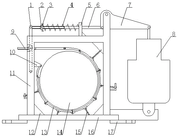
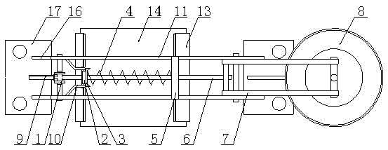
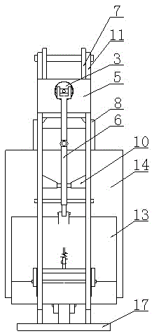
[0024] Depend on Figures 1 to 5 It can be seen that the multi-watt integral brake includes a brake shoe 21, a brake pad 20, a base 16, an electric pusher 8 and a top pressure spring 4, a frame 11 and a pusher are arranged on the base, and a rocker arm is arranged on the frame. 7. The pull rod mechanism composed of push-pull rod 6, connecting rod 9 and lever 1, one end of the pull rod mechanism is connected to the pusher, and the other end is connected to the frame; a brake chain belt 13 formed by five brake tiles is arranged in the frame to make The dynamic chain belt is formed into a circle and floats on the surface of the brake drum 14. One end of the brake chain belt is connected to the frame, and the other end is connected to the connecting rod. Shake to drive the brake chain to move.
[0025] Depend on figure 1 , 6 It can be seen that the pull rod mechanism is composed of a...
PUM
Abstract
The invention discloses a multi-shoe integral brake, belongs to a brake and particularly relates to a brake with a plurality of brake blocks. The multi-shoe integral brake is characterized in that a frame and a pusher are arranged on a base, a draw bar mechanism comprising rocker arms, a push-pull rod, a connecting rod and a lever is arranged on the frame, one end of the draw bar mechanism is connected with the pusher, and the other end of the draw bar mechanism is connected onto the frame; a brake chain is arranged in the frame, at least five brake shoes are linked with one another to form the brake chain, a circumference is formed by the brake chain in an encircled manner and clings to the surface of a brake drum in a floating manner, one end of the brake chain is connected onto the frame, the other end of the brake chain is connected onto the connecting rod, a shaft of the pusher moves up and down, the draw bar mechanism is pushed to swing around fulcrums on the tops of upright columns of the frame, and the brake chain can be driven to act. The multi-shoe integral brake has the advantages that the multi-shoe integral brake can run stably and reliably, shaking of the mechanism can be eliminated, floating clinging can be prevented after the brake chain is separated from the brake drum, a brake friction area can be enlarged, brake torque can be increased, pressure of an ejecting spring is low, power of the pusher can be reduced, a good brake effect can be realized, energy can be saved, and consumption can be reduced; high-temperature failure of brake linings can be prevented, and accordingly consumption of spare parts can be reduced.
Description
technical field [0001] The invention belongs to brakes, in particular to a brake with multiple brake blocks. Background technique [0002] Brakes have a wide range of uses and are used in production equipment in various industries to effectively control the production process and ensure safe operation of equipment and personal safety. At present, the brakes used are mostly composed of components such as bases, brake arms, levers and pull rods. The intelligent brake disclosed by China Intellectual Property (CN103195847A), the first and second brake arms are hinged on the base, the brake arm is provided with a brake pad, and the brake spring is sequentially arranged on the right side base of the first brake arm The assembly and the pusher, the brake spring assembly and the top end of the pusher are all hinged on the lever, the other end of the lever is respectively hinged with the first brake arm and the pull rod through different hinge shafts, and the other end of the pull r...
Claims
Application Information
Patent Timeline
Application Date:The date an application was filed.
Publication Date:The date a patent or application was officially published.
First Publication Date:The earliest publication date of a patent with the same application number.
Issue Date:Publication date of the patent grant document.
PCT Entry Date:The Entry date of PCT National Phase.
Estimated Expiry Date:The statutory expiry date of a patent right according to the Patent Law, and it is the longest term of protection that the patent right can achieve without the termination of the patent right due to other reasons(Term extension factor has been taken into account ).
Invalid Date:Actual expiry date is based on effective date or publication date of legal transaction data of invalid patent.