An inner cavity hook groove and plane detection centering device

A hook groove and plane technology, which is applied in the field of inner cavity hook groove and plane detection and centering device, to achieve the effects of improving processing and detection efficiency, reducing unqualified products, and fast and accurate detection

Active Publication Date: 2016-09-14
NANJING TURBINE & ELECTRIC MASCH (GRP) CO LTD
View PDF5 Cites 0 Cited by
  • Summary
  • Abstract
  • Description
  • Claims
  • Application Information

AI Technical Summary

Problems solved by technology

[0003] The purpose of the present invention is to provide an inner cavity hook groove and a plane detection and centering device, improve the detection and centering accuracy of the compound ring T-shaped ring groove and other complex parts, improve the detection and centering efficiency, and solve the installation and positioning of various parts Technical Problems in Rework and Inspection of Complicated Ring Groove

Method used


Image

  • An inner cavity hook groove and plane detection centering device
  • An inner cavity hook groove and plane detection centering device
  • An inner cavity hook groove and plane detection centering device

Examples


Embodiment 1

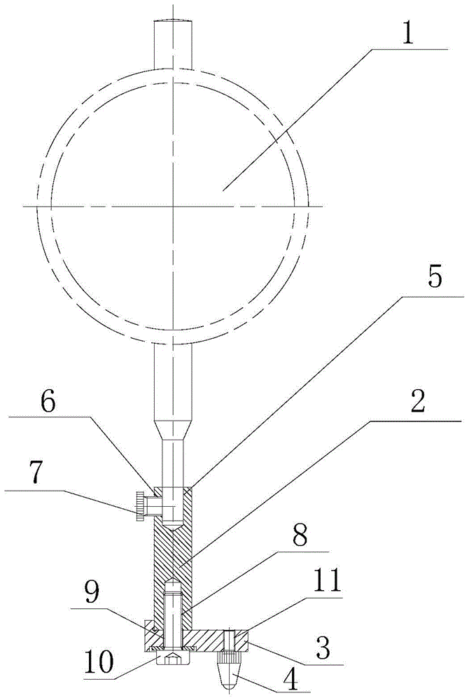
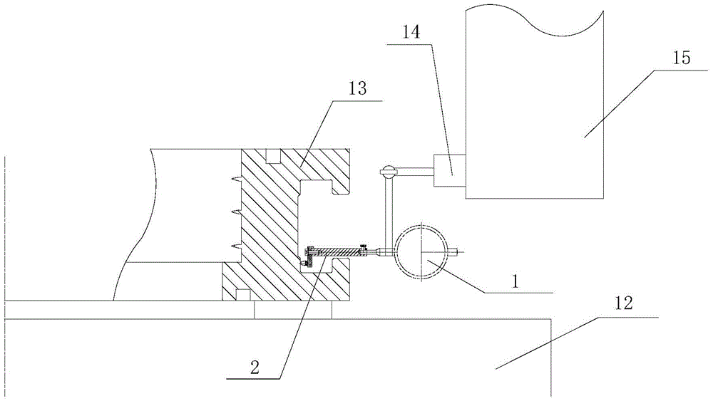
[0023] like figure 1 The inner cavity hook groove and plane detection and centering device shown include a dial indicator 1, a connecting support 2 and a contact connecting plate 3. One end of the connecting support 2 is connected to the detection rod of the dial indicator 1, and the other end is connected to the contactor connecting plate 3. One end of the head connection plate 3 is connected, the connection support 2 is perpendicular to the contact connection plate 3, the other end of the contact connection plate 3 is provided with a contact 4, and the contact connection plate 3 is in the shape of a "one", so The contact 4 is perpendicular to the contact connecting plate 3 , and the contact 4 and the connecting support 2 are arranged on both sides of the contact connecting plate 3 respectively.

[0024] The connection mode of described connecting support 2 and the measuring rod of dial indicator 1 is: the end that connecting supporting 2 is connected with the measuring rod o...

Embodiment 2

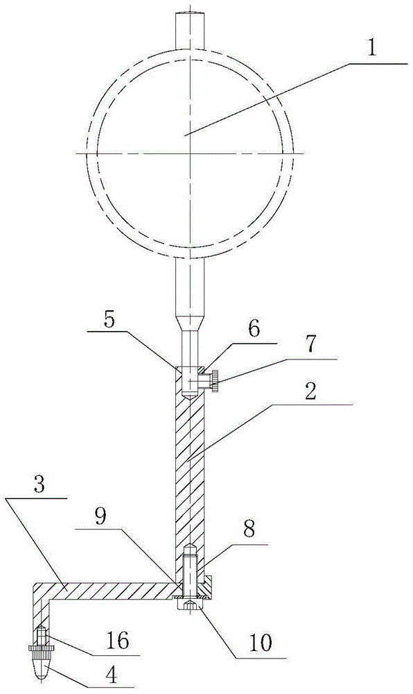
[0029] like image 3 The inner cavity hook groove and plane detection and centering device shown include a dial indicator 1, a connecting support 2 and a contact connecting plate 3. One end of the connecting support 2 is connected to the detection rod of the dial indicator 1, and the other end is connected to the contactor connecting plate 3. One end of the head connection plate 3 is connected, the connection support 2 is perpendicular to the contact connection plate 3, and the other end of the contact connection plate 3 is provided with a contact 4, and the contact connection plate 3 is in an "L" shape. The end of the contact connecting plate 3 connected to the contact 4 is in line with the contact 4, and the contact 4 and the connecting support 2 are arranged on both sides of the contact connecting plate 3 respectively.

[0030] The connection mode of described connecting support 2 and the measuring rod of dial indicator 1 is: the end that connecting supporting 2 is connecte...


PUM


Abstract

The invention discloses an inner cavity groove and plane detection centering device. The device comprises a dial indicator (1) and is characterized in that the device further comprises a connecting support (2) and a contact connecting plate (3). One end of the connecting support (2) is connected with a detection rod of the dial indicator (1), the other end of the connecting support (2) is connected with one end of the contact connecting plate (3), one end of the connecting support (2) is perpendicularly connected with the contact connecting plate (3), and a contact (4) is arranged at the other end of the contact connecting plate (3) and is parallel to the connecting support (2). The device has the advantages that the connecting support is perpendicular to the contact connecting plate, the dial indicator contact is installed on the contact connecting plate, positioning faces of a T-shaped annular groove are arranged in an outer circle, and therefore the contact stretches into the T-shaped annular groove through the contact connecting plate, and the contact makes contact with all the positioning faces of the T-shaped annular groove.

Description

technical field [0001] The invention relates to an inner cavity hook groove and a plane detection and centering device, which belongs to the field of mechanical processing. Background technique [0002] The compound ring is a key part of the gas turbine, which requires high dimensional accuracy and position accuracy, and its structure is relatively complicated. Since it is installed in the gas turbine cylinder by the T-shaped ring groove, the requirements for the positioning surface of the T-shaped ring groove are very high. Once the error is too large, it will affect the installation accuracy of the compound ring in the turbine cylinder, and then affect the gap between the compound ring air seal and the turbine rotor, resulting in repair. For this type of components that are installed and positioned through complex ring grooves, we must try our best to ensure their installation accuracy, which puts forward very high precision requirements for the dimensional accuracy and sh...

Claims


Application Information

Patent Timeline
Patent Type & Authority Patents(China)
IPC IPC(8): G01B5/00
Inventor 柳政朱丹付刚王源陈顺飞张宏伟
Owner NANJING TURBINE & ELECTRIC MASCH (GRP) CO LTD
Why Eureka
Try Eureka