Graph cut method for contrasting filled and excavated space by using three-dimensional triangulation network

A technology of triangulation and space, applied in the field of 3D modeling, can solve the problems of precision influence, inability to build, complex reality model, etc., achieve high precision and avoid decomposition

Active Publication Date: 2014-07-16
WUHAN UNIV
2 Cites 10 Cited by

AI-Extracted Technical Summary

Problems solved by technology

This method has high calculation accuracy, but there are also some problems: when using the projection method to construct the TIN, there are differences in the TIN constructed by different projection surfaces (even wrong TIN), which has a great impact on the accuracy;...

Abstract

The invention relates to a graph cut method for contrasting filled and excavated space by using a three-dimensional triangulation network. According to the method, the three-dimensional triangulation network is directly constructed on the basis of the graph cut method, and network construction problems are regarded as mark optimization problems. Firstly, initial landform splashes and actual landform splashes are obtained and combined, and then a normal vector of each splash is estimated; tetrahedrons are constructed through the combined splashes by the adoption of the point-by-point insertion algorithm, the space is decomposed, and the tetrahedrons contain the triangulation network which users want to obtain; according to intersecting information of the normal vectors of the splashes and the tetrahedrons, and area information of each triangular surface of the tetrahedrons, the weight of an s-t graph is added; final surfaces are obtained by the minimum cut-maximum flow algorithm, the filled and excavated space is obtained, and the quantity of filled and excavated earth work is obtained by adding up the volumes of the tetrahedrons. According to the graph cut method, projection on a two-dimensional plane is not needed, and the defects caused when the triangulation network is constructed with a two-dimensional projection method are overcome; the quantity of earth work is calculated through the tetrahedrons, so that precision is higher.

Application Domain

3D modelling

Technology Topic

Optimization problemMinimum cut +6

Image

  • Graph cut method for contrasting filled and excavated space by using three-dimensional triangulation network
  • Graph cut method for contrasting filled and excavated space by using three-dimensional triangulation network
  • Graph cut method for contrasting filled and excavated space by using three-dimensional triangulation network

Examples

  • Experimental program(1)

Example Embodiment

[0029] The invention is a three-dimensional triangulation method based on Delaunay tetrahedron and graph cut method. The technical process is as follows Image 6 Shown. Use the original terrain scatter points and the actual terrain scatter points to decompose the space with Delaunay tetrahedrons. The vertices and directed edges of the dual graph of Delaunay tetrahedron (Voronoi diagram) correspond to the vertices and directed edges in the st graph, and the vertices represent Delaunay Tetrahedron, with directed edges means triangular faces with directions. We regard the calculation problem of filling and digging the space as an energy function minimization problem. The energy function includes the normal vector energy term and the triangle area energy term. According to the normal vector information and the triangle area information, the weight of the st map is added. The solution process is to find the st map The minimum cut of, the globally optimized labeled tetrahedron is s or t.
[0030] Based on the above principles, the embodiments of the present invention will be described in detail with reference to the drawings.
[0031] 1. Get scattered data
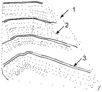
[0032] 1.1 Measure the actual surface of a certain area to obtain the actual measurement scatter points and the measurement boundary scatter points. If there are topographic feature lines on the excavated slope, obtain the topographic feature measurement scatter points, such as figure 1 Shown. The purpose of obtaining terrain feature measurement scattered points is to express the three-dimensional model more accurately, so as to obtain a more accurate amount of fill and excavation.
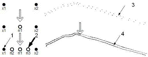
[0033] 1.2 Encrypt the topographic feature measurement points so that the average distance between adjacent topographic feature measurement points is one-third of the average distance of the actual surface measurement points, the purpose is to more accurately restore the shape of the terrain, such as figure 2 Shown.
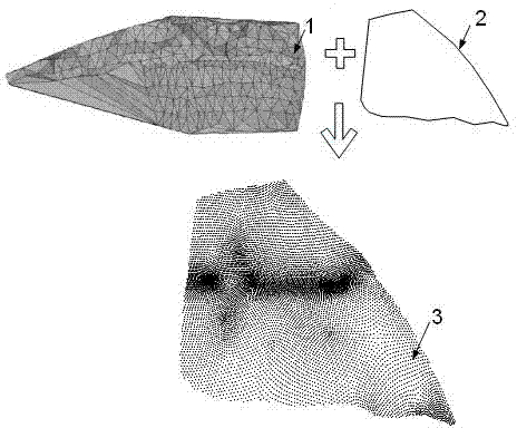
[0034] 1.3 Split the original terrain triangulation, the purpose is that smaller triangles can approach the measurement boundary more accurately, the measurement boundary and the original terrain triangulation are projected to the XY plane, and the vertices of the triangulation within the boundary are taken out as the original terrain measurement Scattered points, such as image 3 Shown. The division algorithm is to divide the sides of each triangle, take the midpoint of the triangle side as the division point, and find the triangles t1 and t2 where this side is located. The coordinates of the division point are the average of the four vertices of the triangles t1 and t2, such a The triangle is divided into four smaller triangles.
[0035] 1.4 Combine the scattered points of the actual survey and the scattered points of the original topographic survey to estimate the normal vector of each scattered point, such as Figure 4 Shown. To this end, for each point p in the point cloud, the k nearest neighbor points are obtained, and then a local plane P is calculated for these points by least squares. This plane can be expressed as follows:
[0036] P ( n , d ) = arg min ( n , d ) X i = 1 k ( n · p i - d ) 2
[0037] Where n is the normal vector of the plane P, and d is the distance from P to the origin of the coordinate.
[0038] 2. Construct Delaunay tetrahedron
[0039] The purpose of constructing the Delaunay tetrahedron is to decompose the space, and use the point-by-point insertion algorithm to construct the Delaunay tetrahedron from the original topographic survey scattered points and the actual survey scattered points. The vertices and directed edges of the dual graph of the Delaunay tetrahedron (that is, the Voronoi graph) correspond to the vertices and directed edges of the s-t graph. The vertices of the s-t graph represent tetrahedrons, and the directed edges represent triangular faces with directions.
[0040] 3. Add the weight of s-t
[0041] 3.1 Add weights based on normal vectors. The principle of s-t diagram based on surface reconstruction is shown in Figure 5 Here, the black solid circle point P represents the tetrahedron vertex, the black dashed line L is the normal vector n of the black solid circle point P, and the black hollow circle point P′ is the point where the tetrahedron vertex moves by a distance in the opposite direction of the normal vector. Locate the tetrahedron T'where the point P'is located, connect it to the end point of t in the st map and give it a weight of t, add all the weights of t according to this method; start from the point P and find the method to be used along the normal vector n The triangle T that the vector crosses i Until the tetrahedron traversed is an infinite tetrahedron or a t tetrahedron, add T i The weight of the directed edge of the corresponding s-t graph; the last tetrahedron T traversed by the normal vector n is connected to s in the s-t graph, and s weight is assigned, and all edge weights and s weights are added in sequence.
[0042] 3.2 Add weights based on the area of ​​the triangle. Calculate the area of ​​each triangle in the Delaunay tetrahedron, add it as a weight to the corresponding directed edge in the st diagram, and calculate the average area of ​​each triangle in the Delaunay tetrahedron, and add it as a weight to all t weights Value.
[0043] 3.3 Reasonable distribution of λ normal And λ area So far, the construction of the s-t graph is completed.
[0044] 4. Solve the fill and cut space
[0045] Use the maximum flow minimum cut algorithm to relabel the state where each vertex in the st graph is connected to s and t. After relabeling, the vertices that are not connected to s and t are defined as t vertices, so that the vertices in the st graph are divided into two categories : S vertex and t vertex. We keep the Delaunay tetrahedrons corresponding to the t vertices, and these reserved tetrahedrons are the fill and cut spaces, such as Figure 7 Shown. The amount of earthwork V is the sum of the volume of each tetrahedron. The amount of earthwork is calculated as follows:
[0046] V = X i A I v i = 1 3 X i A I s i h i
[0047] I is a collection of tetrahedrons in the fill and excavation space;
[0048] v i Is the volume of a tetrahedron;
[0049] s i Is the area of ​​the bottom of the tetrahedron;
[0050] h i Is the height of the tetrahedron.

PUM

no PUM

Description & Claims & Application Information

We can also present the details of the Description, Claims and Application information to help users get a comprehensive understanding of the technical details of the patent, such as background art, summary of invention, brief description of drawings, description of embodiments, and other original content. On the other hand, users can also determine the specific scope of protection of the technology through the list of claims; as well as understand the changes in the life cycle of the technology with the presentation of the patent timeline. Login to view more.

Similar technology patents

Lithium metal battery charging and discharging method

PendingCN114824522Aavoid decompositionpromote decomposition
Owner:安徽盟维新能源科技有限公司

Improved large ozone generator

PendingCN113184811AImprove cooling effectavoid decomposition
Owner:宿州龙润生物科技有限公司

Microbicidal and algicidal composition

InactiveCN101081710Aavoid decompositionResidual chlorine concentration does not decrease
Owner:KURITA INDUSTRIAL CO LTD

Sealed liquid ammonia pump for conveying liquid ammonia

ActiveCN114810674AImprove the environment inside the pumpavoid decomposition
Owner:SICHUAN MIANZHU CHUANRUN CHEM CO LTD

Classification and recommendation of technical efficacy words

  • avoid decomposition
  • High precision

Composite isatis root orally disintegrating tablet and preparation method thereof

InactiveCN101396382Aavoid decompositionIncrease content
Owner:上海市脑血管病防治研究所

Umbilicus plastering powder for defaecation

InactiveCN101293066Aavoid decompositionovercoming difficulty in taking medicine
Owner:周鑫

Continuous preparation method of 1-acetyl-1-chlorocyclopropane

InactiveCN104672074Areduce contact timeavoid decomposition
Owner:XIAN MODERN CHEM RES INST

Method for synthesis of high purity trimethyl silicon based imidazole

ActiveCN101367828Aavoid decompositionReduces production of imidazoles and silyl ethers
Owner:ZHEJIANG UNIV +1

Artwork adhesive

InactiveCN107254025AThoroughly dissolvedavoid decomposition
Owner:阜南县中信柳木工艺品有限公司

Method for forecasting short-term power in wind power station

InactiveCN102102626AHigh precision
Owner:NORTH CHINA ELECTRIC POWER UNIV (BAODING) +1

Numerical control machine tool wear monitoring method

InactiveCN102091972AHigh precisionReal-time monitoring of tool wear
Owner:HUAZHONG UNIV OF SCI & TECH +1

Advertisement recommendation method and apparatus

ActiveCN104965890AHigh precisionPrecise screening
Owner:SHENZHEN TENCENT COMP SYST CO LTD
Why Eureka
Try Eureka