Worm gear mechanism

A worm gear and worm technology, applied in steering mechanism, power steering mechanism, electric steering mechanism, etc., to achieve the effect of increasing contact area, improving durability and reducing frictional resistance

Inactive Publication Date: 2014-07-16
HONDA MOTOR CO LTD
View PDF6 Cites 0 Cited by
  • Summary
  • Abstract
  • Description
  • Claims
  • Application Information

AI Technical Summary

Problems solved by technology

[0006] However, in the technique of the above-mentioned Patent Document 1, there is room for improvement in suppressing the wear of the tooth surface of the resin-made worm wheel.

Method used


Image

  • Worm gear mechanism
  • Worm gear mechanism
  • Worm gear mechanism

Examples


Embodiment 1

[0032] A method of manufacturing the electric power steering apparatus including the worm gear mechanism according to the first embodiment and the worm gear mechanism will be described.

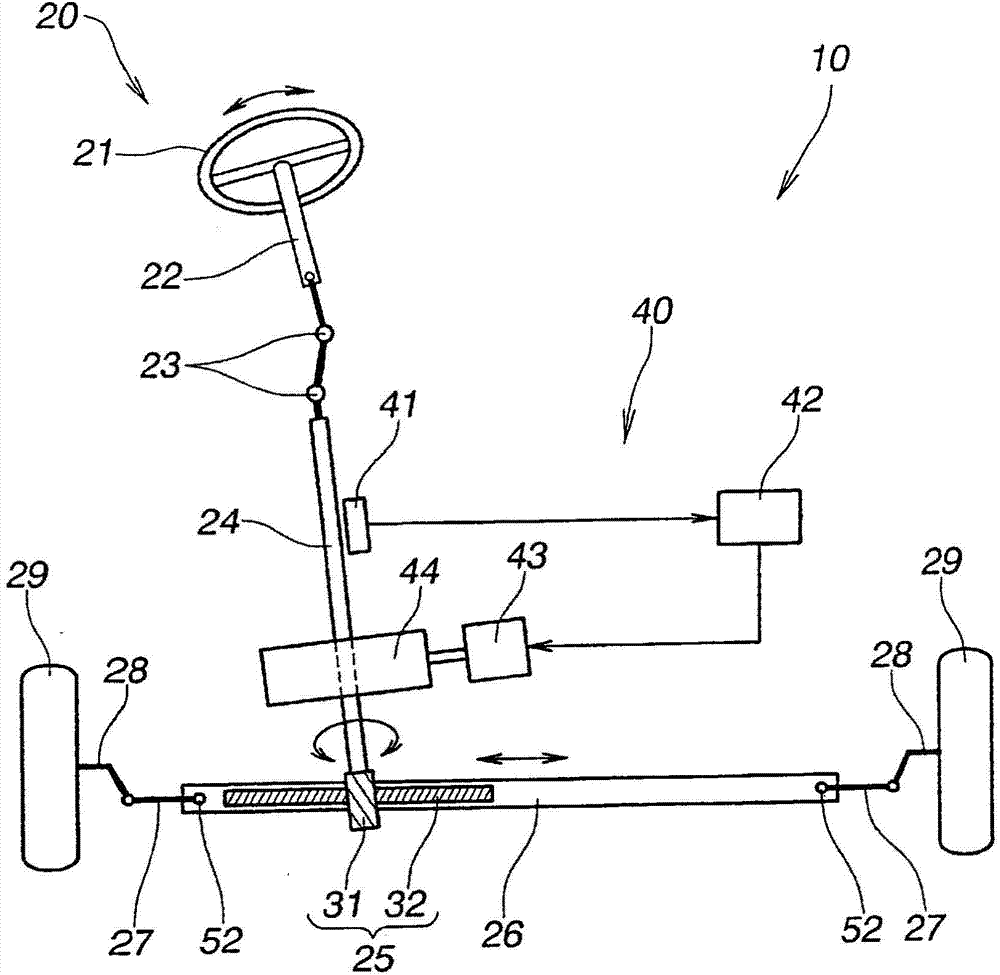
[0033] Such as figure 1 As shown, the electric power steering device 10 based on Embodiment 1 includes: a steering system 20 from the steering wheel 21 of the vehicle to the steering wheels 29, 29 (for example, front wheels) of the vehicle; Torque mechanism 40.

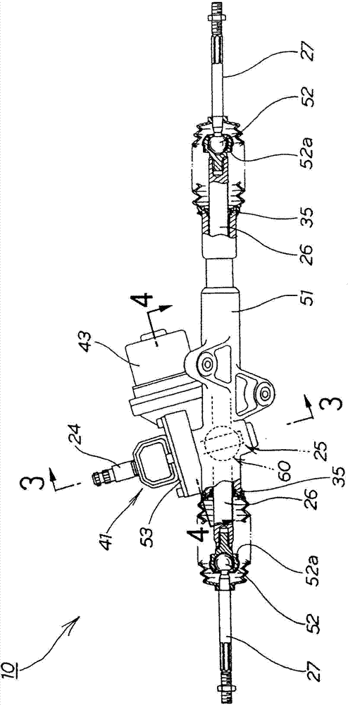
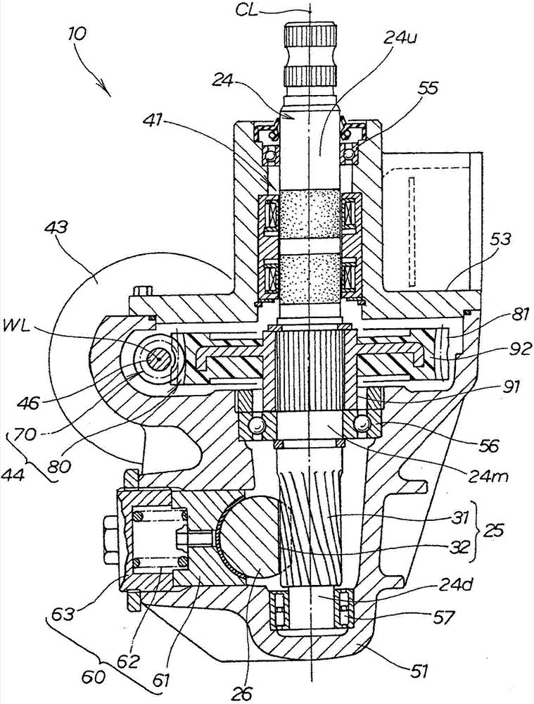
[0034] In the steering system 20 , a pinion shaft 24 (rotation shaft 24 ) is connected to the steering wheel 21 via a steering shaft 22 and universal joints 23 , 23 , and a rack shaft is connected to the pinion shaft 24 via a rack-and-pinion mechanism 25 . 26 , left and right steering wheels 29 , 29 are connected to both ends of the rack shaft 26 via left and right tie rods 27 , 27 and steering knuckles 28 , 28 .

[0035] The rack-and-pinion mechanism 25 includes a pinion 31 formed on the pinion shaft 24 and a rack 32 formed on the...

Embodiment 2

[0077] Next, combine Figure 11 Next, a method of manufacturing the worm gear mechanism 44A based on the second embodiment will be described. Figure 11 (a) with Figure 9 (a) is shown correspondingly. Figure 11 (b) with Figure 9 (b) is shown correspondingly.

[0078] The worm gear mechanism 44A of the second embodiment has actual meshing concave portions 81drA formed on the tooth surfaces 81a, 81a of the teeth 81 of the worm wheel 80 . The other configurations shown in the second embodiment are substantially the same as those in the first embodiment, and are given the same reference numerals and descriptions thereof are omitted.

[0079] in other words, Figure 9 The actual meshing concave portion 81dr of the illustrated embodiment 1 is formed on a part of the tooth surface 81a. In contrast, based on Figure 11 The actual meshing concave portion 81drA of the second embodiment shown in (a) and (b) is formed over the entire range of the tooth surface 81a.

[0080] The...


PUM


Abstract

The invention provides a worm gear mechanism. The worm gear mechanism (44) is configured to comprise a worm (70) which is connected to an electric motor, and a worm wheel (80) engaged with the worm. In the worm wheel (80), at least a tooth flank (81a) is formed of a resin material. In the tooth flank (81a), an engagement recess (81dr), which is based on a the trajectory of a contact point being in contact with a tooth (71) of the worm (70) according to a rotation of the worm (70), is formed by injection molding only, together with the tooth flank, using a mold (100). The engagement recess (81dr) comprises a plurality of points (P1a-P9a) which are recessed the most in a the direction of a tooth of the tooth flank of the worm wheel correspondingly to the trajectory of the contact point with which the most convex portion of the tooth (71) of the worm (70) is in contact. A line (Loa) which connects the plurality of points intersects with respect to a tooth width center line (Ct) of the tooth flank (81a) of the worm wheel (80).

Description

technical field [0001] The invention relates to an improved worm gear mechanism. Background technique [0002] A worm gear mechanism is used in an electric power steering device. This worm gear mechanism is composed of a worm connected to an electric motor and a worm wheel connected to a load. The torque generated by the electric motor is transmitted from the worm to the load via the worm gear. [0003] In recent years, there has been an increasing demand for downsizing and weight reduction of electric power steering devices, and higher output of electric motors has been sought. In order to realize the miniaturization of the electric power steering device, the miniaturization of the worm gear mechanism is essential. However, if only the worm gear mechanism is downsized without reducing the torque generated by the electric motor, the surface pressure acting on the teeth of the worm and the teeth of the worm wheel will increase. [0004] On the other hand, by forming the t...

Claims


Application Information

Patent Timeline
IPC IPC(8): F16H1/16B62D5/04F16H55/08F16H55/22
CPCB62D5/0409F16H1/16F16H55/0853F16H55/22B62D5/0421F16H2055/065Y10T74/18792F16H1/203F16H55/06
Inventor 田中阳介清水康夫
Owner HONDA MOTOR CO LTD
Why Eureka
Try Eureka