Air purifying device

An air purification device and air purification technology, which is applied in the field of air purification, can solve the problems of airflow path short circuit, high noise, high resistance, etc., and achieve the effects of increasing the air volume of purification, reducing noise, and reducing energy consumption

Inactive Publication Date: 2014-07-23
刘宏志
View PDF10 Cites 14 Cited by
  • Summary
  • Abstract
  • Description
  • Claims
  • Application Information

AI Technical Summary

Problems solved by technology

[0013] 1. It has a shell or a specific overall structure, which is used to install components, form airflow channels and similar purposes. This problem exists in the above-mentioned prior art. This problem limits the expansion of air volume and is also useful for performance optimization in various aspects. limit;
[0014] 2. Take the combination of "fan + filter corresponding to the fan" as the basic functional unit, and use different combination numbers and forms to obtain different effects, such as existing technologies 2, 4, 5, 6, and 7. This problem, in this way of thinking, there is always a corresponding relationship between a certain airflow drive device and a specific air filter, which limits the performance improvement in many ways;
[0015] 3. The positions of the air inlet and outlet are adjacent and the airflow cannot be effectively separated, resulting in a short circuit in the airflow path. When used indoors, the overall air circulation and filtration of the working space cannot be effectively realized. This problem is installed at the air outlet. Filters are especially obvious, as existing technologies 1 and 3 have this problem;
[0016] 4. It is difficult to use a real high-efficiency air filter or its performance is low in terms of air volume and lifespan
High-efficiency air filters can provide excellent filtration efficiency, but the resistance is relatively high. As far as the structure of most existing air purification devices is concerned, direct use of real high-efficiency air filters will have low air volume, high noise, and short life Many other problems, practicality is not enough
[0017] The above-mentioned existing technologies, none of them have been able to optimize as many aspects as possible in terms of air volume, noise, efficiency, volume, energy consumption, airflow path, etc., and at the same time minimize the unfavorable factors brought by the optimization method. Some performance indicators have been improved, but caused other problems or retained the deficiencies of the original technology
Existing technologies for air purification devices still have much room for improvement

Method used


Image

  • Air purifying device
  • Air purifying device
  • Air purifying device

Examples


Embodiment 1

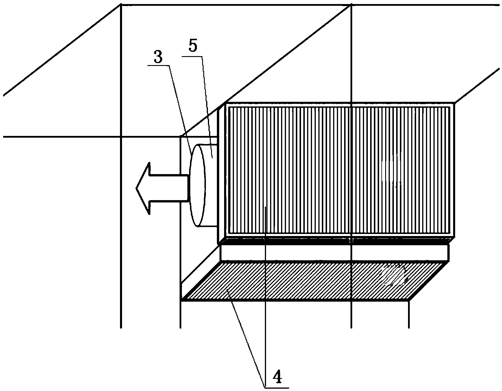
[0059] Such as figure 1 As shown, the air cleaning device is installed in the corner of the wall, and the air cleaning device includes a fan 5, an air filter 4 and a frame of a hollow structure; the cross-sectional shape of the frame is a quadrilateral, and the frame includes four sides and two end faces 2, and the two sides of the frame An air filter 4 is installed on the top, and the other two sides can be blocked with a flat plate or a wall; one end face 2 of the frame is a flat plate, and the other end face 2 can also be a flat plate or a wall. The body or the plate is provided with a purified air outlet 1; the fan 5 is arranged inside the frame, and the air outlet 3 of the fan 5 is connected with the purified air outlet 1. The air filter 4 covers the entire side. The air filter 4 is a filter with a single filtration efficiency above the sub-high efficiency specified in GB / T14295-2008.

Embodiment 2

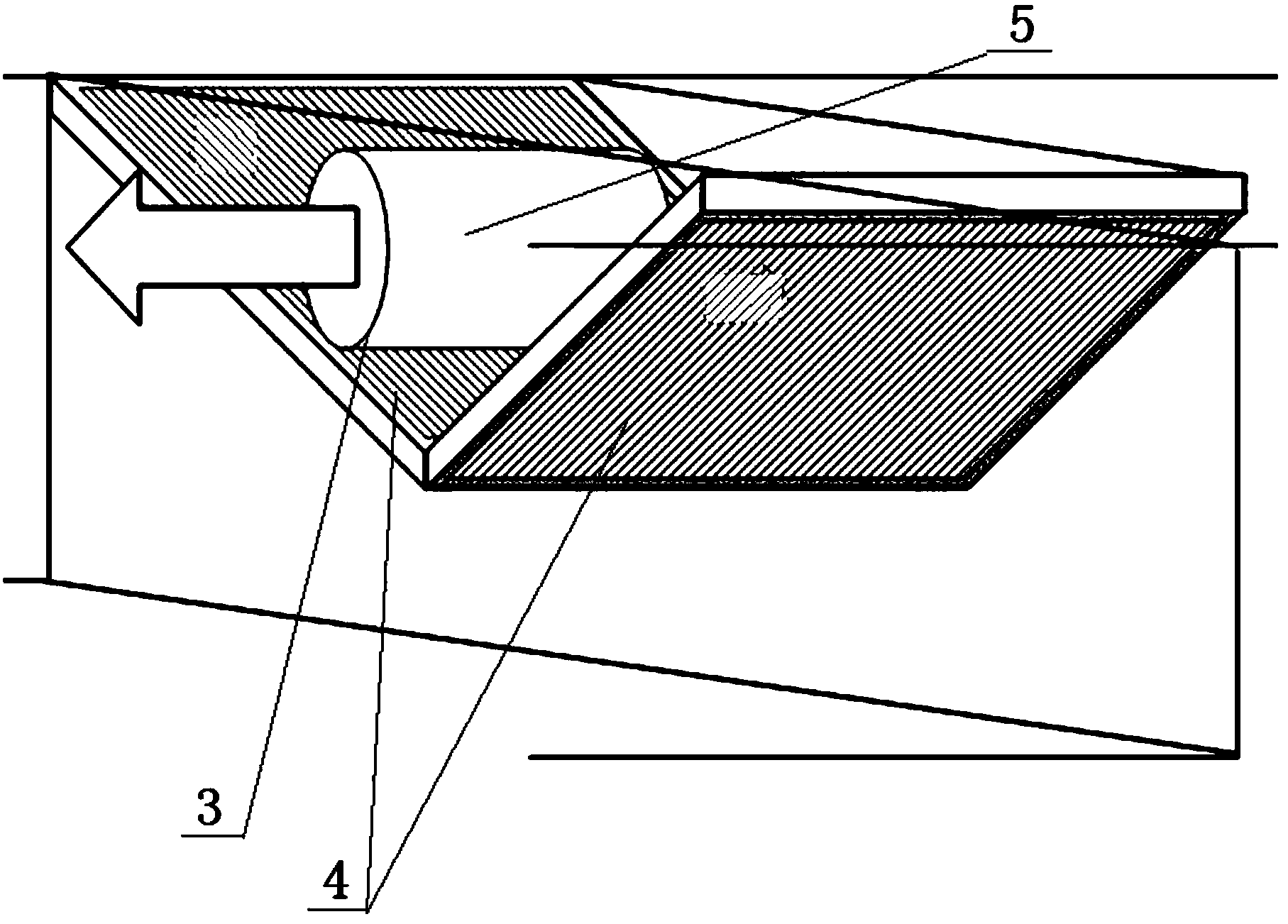
[0061] Such as figure 2 As shown, the air cleaning device is installed on the wall, and the air cleaning device includes a blower fan 5, an air filter 4 and a frame of a hollow structure; An air filter 4 is installed on one side, and the other side can be blocked with a flat plate or a wall; one end face 2 of the frame is a flat plate, and the other end face 2 can be a flat plate or a wall, A purified air outlet 1 is provided on the wall or a flat panel; a fan 5 is arranged inside the frame, and an air outlet 3 of the fan 5 is connected to the purified air outlet 1 . The air filter 4 covers the entire side. The air filter 4 is a filter with a single filtration efficiency above the sub-high efficiency specified in GB / T14295-2008.

Embodiment 3

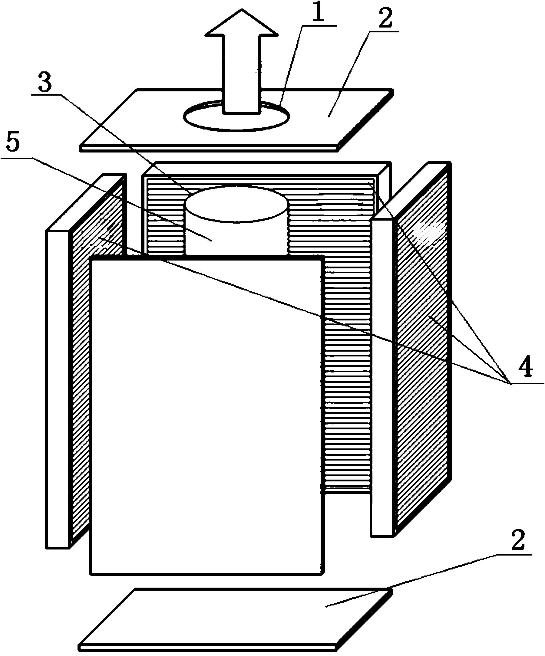
[0063] Such as image 3 As shown, the air cleaning device includes a fan 5, an air filter 4 and a hollow structure frame; the cross-sectional shape of the frame is quadrilateral, the frame includes four sides and two end faces 2, and the air filter 4 is installed on three sides of the frame , the other side is blocked with a flat plate; both end faces 2 of the frame are flat plates, and one end face 2 is provided with a purified air outlet 1; the fan 5 is arranged inside the frame, and the air outlet 3 of the fan 5 is connected with the purified air outlet 1. The air filter 4 covers the entire side. The air filter 4 is a filter with a single filtration efficiency above the sub-high efficiency specified in GB / T14295-2008.


PUM


Abstract

The invention discloses an air purifying device, relates to the technical field of air purification, and provides an air purifying device which is improved comprehensively at the aspects of air volume, noise and efficiency compared with the prior art. The air purifying device comprises a fan, air filters and a framework of a hollow structure, wherein the cross section of the framework is n-sided shaped, wherein n>=3; the framework comprises n lateral surfaces and two end surfaces; at least two lateral surfaces of the framework are provided with the air filters of panel structures; the end surfaces of the framework provided with purified air outlets; the fan is arranged in the framework; an air outlet of the fan is connected with the purified air outlets. According to the invention, the use of the air filters increases, and a sealed space is defined by the air filters; air can enter the sealed space from each air filter; the fan absorb purified air from the sealed space and conveys the purified air to the required position; the air intake resistance is low; performances at each aspect are improved obviously.

Description

technical field [0001] The invention relates to the technical field of air purification, in particular to a high-performance air purification device. Background technique [0002] The problem of fine particle pollution in the air has been gradually recognized by people, and air purification devices such as air purifiers are used more and more. Most air purification devices use a combination of an air filter and an airflow drive device. The airflow drive device drives the air to flow through the air filter to obtain the basic structure of the purification effect. The following part of this specification will refer to this structure as "basic structure". [0003] For an air purification device with a basic structure, air volume, noise, and efficiency are three important performance indicators. The larger the air volume, the better the purification effect, the lower the noise, the better, and the higher the filtration efficiency, the better, but these three performance indicat...

Claims


Application Information

Patent Timeline
Patent Type & Authority Applications(China)
IPC IPC(8): B01D46/00
Inventor 不公告发明人
Owner 刘宏志
Why Eureka
Try Eureka