
A multi-degree-of-freedom manipulator joint based on linear drive of smart materials

A technology of linear drive and intelligent materials, applied in the field of manipulators, can solve the problems of increasing the weight of manipulators, not involving multiple degrees of freedom of manipulators, increasing energy consumption, etc., to achieve increased use value, convenient installation and maintenance, and low cost Effect

Inactive Publication Date: 2015-09-30
HARBIN ENG UNIV
View PDF5 Cites 0 Cited by
  • Summary
  • Abstract
  • Description
  • Claims
  • Application Information

AI Technical Summary

Problems solved by technology

At present, motors are generally used in the design of industrial manipulators. Since motor drive is a form of axial power output, an intermediate mechanism is needed to convert its power to achieve linear output of axial torque. This design idea Increasing the weight of the manipulator increases the energy consumption of its work. At the same time, there is inevitably the defect of working noise, which is a key issue restricting the development of industrial manipulators at this stage; shape memory metal (SMA) is a new type of electric braking intelligent The material can provide a large output force under electric excitation. Unlike the motor drive, SMA can directly realize the linear output of force. This drive method removes the design of the intermediate mechanism, which is a significant innovation compared to the motor drive. However, the current research on the use of SMA materials for manipulators is less, mainly focusing on the research stage of micro-miniature devices, and none of them involve the development of multi-degree-of-freedom manipulators.

Method used


Image

  • A multi-degree-of-freedom manipulator joint based on linear drive of smart materials
  • A multi-degree-of-freedom manipulator joint based on linear drive of smart materials
  • A multi-degree-of-freedom manipulator joint based on linear drive of smart materials

Examples


Embodiment Construction

[0019] The present invention is described in more detail below in conjunction with accompanying drawing example:

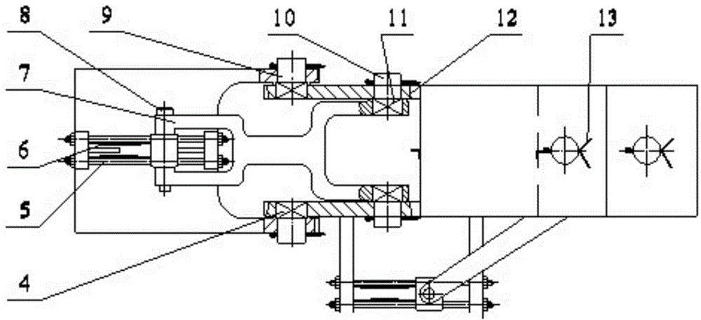
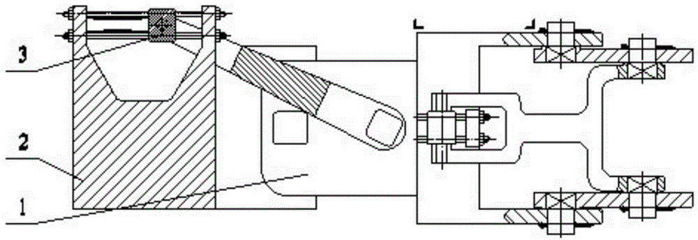
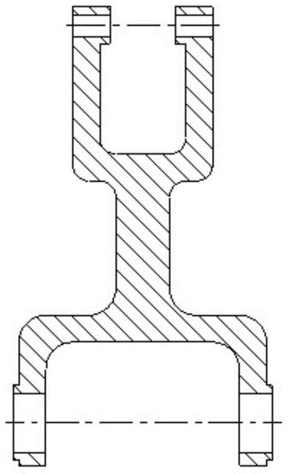
[0020] 1-9, the structure of the present invention mainly includes three parts: plane vertical drive joint I, plane horizontal drive joint II, and plane circumferential drive joint III. A multi-degree-of-freedom manipulator joint structure is obtained by combining and assembling the three parts. It is mainly realized through the combination of plane vertical drive joint I and plane horizontal drive joint II, plane horizontal drive joint II and plane circular drive joint III, that is, I+I+II combination structure, plane vertical drive joint I and plane horizontal drive joint II is assembled and connected through the joint connecting frame 12 and 20, and the plane horizontal driving joint II and the plane circumferential driving joint III are assembled and connected through the joint connecting frame 31 and 37; Four sliding shafts 5 are connected by 4 bolts, one end...


PUM


Abstract

The invention provides a linear-driven multi-freedom-degree mechanical arm joint based on a smart material. Under the excitation of signals, a moving sliding block is pulled by an SMA driving wire to drive a split fork to move so as to pull a joint connecting frame to rotate, and the joint connecting frame is made to swing around the perpendicular plane with a shoulder end brace as a center. At a fore joint driving position, a moving sliding block is pulled by an SMA driving wire to pull a split fork to rotate, and a joint connecting frame is driven to swing around the horizontal plane with a shaft hole of the perpendicular plate side of the joint connecting frame as a center. At two fore joint driving positions, an SAM driving wire on a joint connecting frame drives a moving sliding block to drive the split fork to rotate around an outer side shaft hole of the joint connecting frame so as to drive an axial joint connecting frame to rotate in the axis direction, and the multi-freedom-degree movement of the mechanical arm joint is achieved finally. According to the linear-driven multi-freedom-degree mechanical arm joint based on the smart material, due to the fact that the SMA wires are adopted, the linear output of power driving can be achieved directly, and the defects of energy consumption and noise caused by using a middle mechanism in the axial driving of a traditional motor are overcome.

Description

technical field [0001] The present invention relates to a robot, specifically a mechanical arm. Background technique [0002] At present, with the progress of industrial civilization, the automated industrial assembly line has become an important symbol of industrial civilization. Behind the industrial civilization, industrial manipulators play an increasingly important role. At this stage, relevant scholars at home and abroad have carried out extensive and in-depth research on industrial manipulators. Theoretical exploration and applied research, and successfully achieved remarkable progress in many aspects. On the one hand, industrial manipulators can replace human labor and increase industrial output value; on the other hand, some micro manipulators have important application potential in the fields of medical treatment and robot manufacturing, so the research on industrial manipulators has always attracted the attention of experts and scholars from all over the world. A...

Claims


Application Information

Patent Timeline
Patent Type & Authority Patents(China)
IPC IPC(8): B25J17/00
Inventor 孙壮志赵刚饶宇郭华君李照远李芳隋智阳乔东潘王晶晶王好军
Owner HARBIN ENG UNIV
Learn More