Machining method of assembly line of angular contact ball bearing sleeve ring

A technology of angular contact ball bearings and processing methods, which is applied to bearing components, shafts and bearings, mechanical equipment, etc., can solve the problems of affecting the processing accuracy of rings, low spindle accuracy life, and high manufacturing costs, so as to reduce the intensity of inspection work, The effect of reducing the number of personnel involved and reducing production costs

Active Publication Date: 2014-07-23
ZHEJIANG UTE BEARING
View PDF4 Cites 20 Cited by
  • Summary
  • Abstract
  • Description
  • Claims
  • Application Information

AI Technical Summary

Problems solved by technology

The production efficiency is very low due to the lack of in-line production
[0010] The existing machining method of the outer diameter of the outer ring of the angular contact ball bearing is centerless grinding. Since there is no fixed grinding reference, it is difficult to guarantee the perpendicularity between the outer diameter of the outer ring and the end face
Therefore, when entering the subsequent groove grinding process, the verticality error will further affect the processing accuracy of the ferrule
[0011] In the existing grinding machine equipment used for grinding angular contact ball bearing rings, the workpiece shaft and the main shaft of the grinding wheel dresser are supported by rolling bearings. Due to the contact wear of the rolling bearings, the precision life of the main shaft is low, and the user needs to replace the bearing or the main shaft regularly, resulting in The continuous production stability of the product is affected, the maintenance frequency is high, and the product consistency is difficult to be guaranteed
[0012] Due to the above-mentioned shortcomings in the production of existing angular contact ball bearing rings, the production efficiency of angular contact ball bearings is low and the manufacturing cost is high, which limits the wide application of angular contact ball bearings in the field of high-speed precision machinery

Method used


Image

  • Machining method of assembly line of angular contact ball bearing sleeve ring

Examples


Embodiment Construction

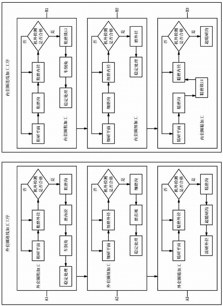
[0037] figure 1 It shows the flow of an embodiment of the processing method for the angular contact ball bearing ring production line of the present invention, including the outer ring connection processing process and the inner ring connection processing process,

[0038] The outer ring connection processing procedure is carried out in the following steps:

[0039] A1: Rough machining of the outer ring: rough grinding plane, rough grinding outer diameter, testing the plane and outer diameter outside the machine, if the test is unqualified, repeat the rough grinding plane and / or rough grinding outer diameter, if the test is qualified, use the grinding wheel shaft to tilt Roughly grind the groove at the angle, then grind the inner diameter and chamfer, and proceed to the next step after stabilization treatment;

[0040] A2: Fine processing of the outer ring: finely grind the plane, finely grind the outer diameter, and test the plane and outer diameter outside the machine. If t...


PUM


Abstract

The invention discloses a machining method of an assembly line of an angular contact ball bearing sleeve ring. The machining method comprises an outer sleeve ring wiring machining procedure and an inner sleeve ring wiring machining procedure, wherein the outer sleeve ring wiring machining procedure comprises the following steps: (A1) carrying out rough machining on an outer sleeve ring; (A2) carrying out micro machining on the outer sleeve ring and (A3) carrying out finish machining on the outer sleeve ring; and the inner sleeve ring wiring machining procedure comprises the following steps: (B1) carrying out rough machining on an inner sleeve ring; (B2) carrying out micro machining on the inner sleeve ring and (B3) carrying out finish machining on the inner sleeve ring. The machining method of the assembly line of the angular contact ball bearing sleeve ring has the advantages of being capable of guaranteeing high accuracy of a product, high in yield and work efficiency, low in production cost and labor intensity and simple to operate.

Description

technical field [0001] The invention relates to a processing method of an angular contact ball bearing, in particular to a processing method used in a production line of an angular contact ball bearing ring. Background technique [0002] Angular contact ball bearing is a kind of rolling bearing, which can bear radial load and axial load at the same time, and has high rotation accuracy and maximum operating speed; the larger the contact angle, the higher the axial load capacity. Under the action of axial force, the angular contact ball bearing's contact angle will increase with the increase of axial force. Compared with traditional deep groove ball bearings, angular contact ball bearings are more suitable for high-speed precision rotating machinery, such as high-speed precision machine tool spindles, aero-engine spindles, high-speed precision motors, etc. In recent years, with the rapid development of the machine tool industry, aviation industry, and motor industry, the dema...

Claims


Application Information

Patent Timeline
Patent Type & Authority Applications(China)
IPC IPC(8): F16C33/64B24B1/00
Inventor 郑子勋熊万里
Owner ZHEJIANG UTE BEARING
Why Eureka
Try Eureka