LED lighting device

A LED lighting and transparent technology, which is applied in the direction of lighting devices, parts of lighting devices, cooling/heating devices of lighting devices, etc., can solve the problems of limited application functions, increased volume of radiators, and heavy weight, etc., to improve light output Efficiency, extended service life, and improved aesthetics

Inactive Publication Date: 2014-07-23
ZHEJIANG ZHONGZHOU LIGHTING TECH
View PDF8 Cites 81 Cited by
  • Summary
  • Abstract
  • Description
  • Claims
  • Application Information

AI Technical Summary

Problems solved by technology

However, the light output of existing LED lighting devices only accounts for 20%-30% of the energy generated, and the remaining 70%-80% of the energy is all used to generate heat without being utilized. Moreover, the unoutputted light A large amount of heat will be generated inside the LED lighting device, which not only reduces the service life of the LED lighting device, but also limits the application function of the LED lighting device due to the inability to use large power
[0003] For this reason, in order to suppress the internal temperature of the LED lighting device from being too high, the heat generated by the LED light-emitting device installed in the LED lighting device is usually conducted to the outside of the LED lighting device by means of a heat sink. However, since the heat dissipation efficiency of the heat sink depends on The size of its surface area, that is: the larger the surface area of ​​the heat sink, the higher the heat dissipation efficiency, and vice versa, the lower. Therefore, the volume of the heat sink often limits the shape, size and weight of LED lighting devices, especially in LED lighting. When the device needs to use higher power, due to the more heat generated inside it, the volume of the heat sink must be increased accordingly, which leads to LED lighting devices compared with traditional lighting devices such as incandescent lamps. The appearance is quite different, and the LED lighting device has defects such as large size and heavy weight, which further reduces the aesthetics, safety and installation convenience of the LED lighting device

Method used


Image

  • LED lighting device
  • LED lighting device
  • LED lighting device

Examples


no. 1 example

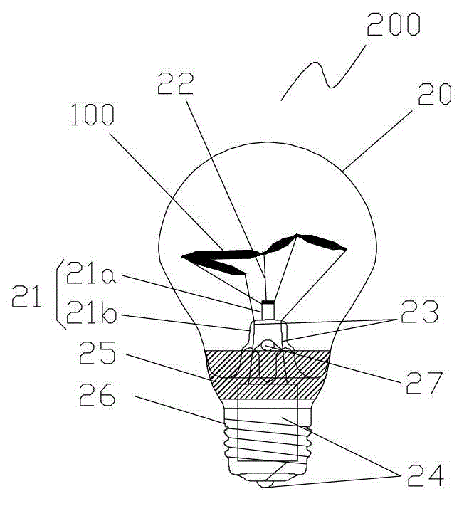
[0040] Please also refer to Figure 1A to Figure 1C , which shows the structure of the LED lighting device provided by the first embodiment of the present invention, the LED lighting device 200 in this embodiment includes a transparent housing 20 , an LED light emitting device 100 and a bracket 21 . Wherein, the transparent shell 20 adopts a shell structure similar to that of a traditional incandescent lamp shell, and the bracket 21 and the transparent shell 20 form a closed cavity. Specifically, the bracket 21 includes a pillar 21a and a base 21b, wherein the base 21b is disposed in the cavity and is located at the bottom of the transparent casing 20, and the base 21b and the transparent casing 20 form a closed cavity; the pillar 21a is disposed on the upper surface of the base 21b , and support leads 22 are provided on the pillars 21a to support the LED light-emitting devices 100 inside the cavity, and when there are multiple LED light-emitting devices 100, multiple LED ligh...

no. 2 example

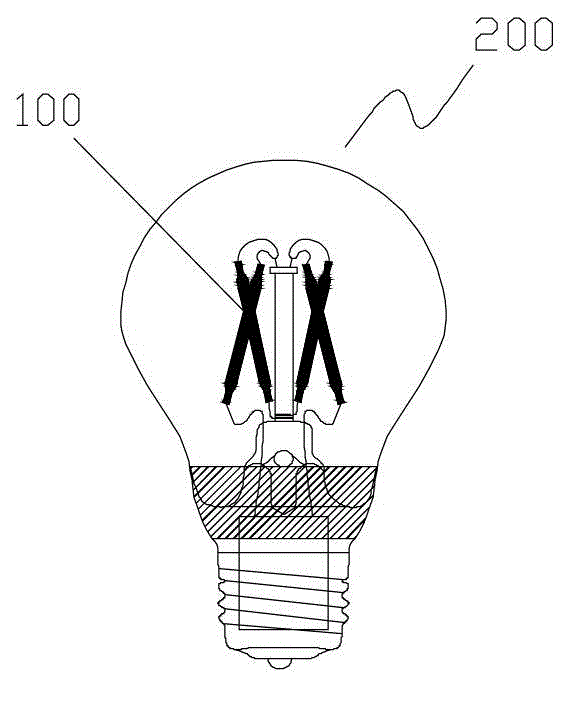
[0060] see image 3 , which shows the structure of the LED lighting device provided by the second embodiment of the present invention, similar to the aforementioned first embodiment, the LED lighting device 200 provided by the second embodiment also includes a transparent housing 20, an LED light emitting device 100 and a bracket 21 . Among them, the structure and shape of the transparent casing 20 and the bracket 21 and the way of filling the cavity formed by the two with inert gas, the way of electrically connecting the LED lighting device 200 to the power supply, the specific structure of the LED light emitting device 100 and the lighting of multiple LEDs. The way of arrangement of the devices 100 in the transparent casing 20 is similar to the above-mentioned first embodiment, and will not be repeated here. Parts of the second embodiment different from the first embodiment will be described in detail below.

[0061] In the second embodiment, a transparent fluorescent laye...

no. 3 example

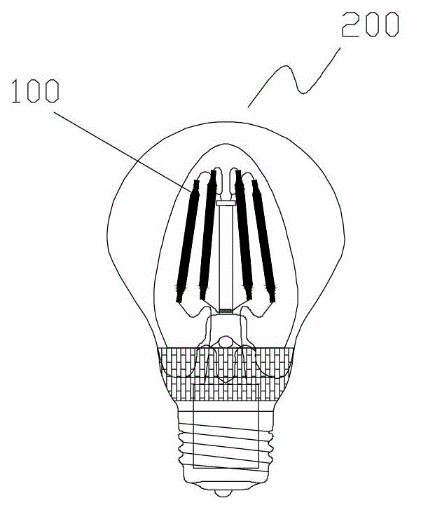
[0063] Similar to the aforementioned first and second embodiments, the LED lighting device 200 provided by the third embodiment also includes a transparent casing 20 , an LED light emitting device 100 and a bracket 21 . Among them, the structure and shape of the transparent casing 20 and the bracket 21 and the way of filling the cavity formed by the two with inert gas, the way of electrically connecting the LED lighting device 200 to the power supply, the specific structure of the LED light emitting device 100 and the lighting of multiple LEDs. The arrangement of the devices 100 in the transparent casing 20 is similar to the first and second embodiments described above, and will not be repeated here. The parts of the third embodiment that are different from the first and second embodiments will be described in detail below.

[0064] see Figure 4A to Figure 4I , which shows the specific structure of the LED light emitting device of the LED lighting device provided by the thir...


PUM


Abstract

The invention relates to the field of LED lighting, and particularly provides an LED lighting device. The LED lighting device comprises a transparent outer shell, an LED luminescent device and a support, wherein the transparent outer shell and the support form a closed cavity and the LED luminescent device is located inside the cavity and fixed onto the support. The LED lighting device is characterized in that the cavity is filled with inert gas which is used for transmitting heat generated by the LED luminescent device to the outer portion of the transparent outer shell. According to the LED lighting device, through the inert gas arranged in the cavity in a filled mode, the heat generated by the LED luminescent device can be transmitted to the outer portion of the LED lighting device without adopting a heat dissipation body, and therefore the shape, the size and the weight of the LED lighting device cannot be limited by the heat dissipating body. Thus, the attractiveness, the safety and the installation convenience of the LED lighting device can be improved.

Description

technical field [0001] The invention relates to the field of LED lighting, in particular to an LED lighting device. Background technique [0002] In recent years, with the trend of energy conservation and environmental protection becoming more and more significant, LED lighting devices have replaced incandescent lamps and fluorescent lamps, and even high-power light sources such as iodine-tungsten lamps and high-pressure sodium lamps have begun to develop from local applications, especially in the field of lighting. , LED lighting devices are more and more widely used, and are regarded as one of the main light sources of future lighting. However, the light output of existing LED lighting devices only accounts for 20%-30% of the energy generated, and the remaining 70%-80% of the energy is all used to generate heat without being utilized. Moreover, the unoutputted light A large amount of heat will be generated inside the LED lighting device, which not only reduces the service...

Claims


Application Information

Patent Timeline
Patent Type & Authority Applications(China)
IPC IPC(8): F21S2/00F21V29/00H01L33/64F21Y101/02F21V29/503
CPCF21V3/00F21V29/85F21K9/232F21Y2115/10F21Y2107/00H01L2224/48137
Inventor 朱晓飚
Owner ZHEJIANG ZHONGZHOU LIGHTING TECH
Why Eureka
Try Eureka