Pressure friction plate braking type real rail vehicle bump testing system

A test system and impact test technology, which is applied in vehicle testing, machine/structural component testing, measuring devices, etc., can solve the problems of high energy level, large mass, and inability to directly use for reference during impact, and achieve a scientific and reasonable structure , easy operation effect

Active Publication Date: 2014-07-23
CENT SOUTH UNIV
View PDF8 Cites 4 Cited by
  • Summary
  • Abstract
  • Description
  • Claims
  • Application Information

AI Technical Summary

Problems solved by technology

[0005] The two technical solutions disclosed above, although they can be applied in the automotive field, they cannot be directly used in the impact test of rail vehicles.
The fundamental reason is the particularity of the structure of rail vehicles, which are large in size, mass, and large

Method used


Image

  • Pressure friction plate braking type real rail vehicle bump testing system
  • Pressure friction plate braking type real rail vehicle bump testing system
  • Pressure friction plate braking type real rail vehicle bump testing system

Examples


Example Embodiment

[0053] Example 1:

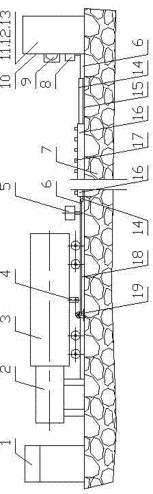
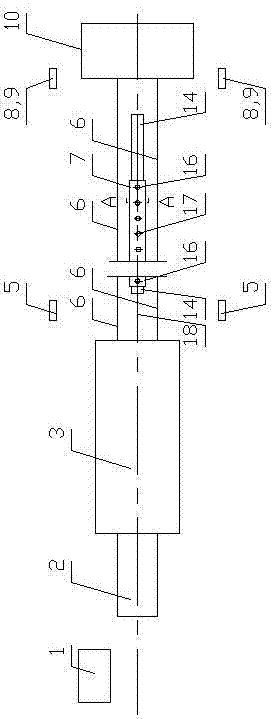
[0054] A steel rail 6 is set on the foundation 7 between the launcher 2 and the impact wall 10; the real vehicle 3 is placed on the steel rail 6, and the real vehicle 3 is installed with the launcher 2 facing away from the end of the impact wall 10; The speed measuring device 8 and the high-speed photography device 9, the vertical line of the impact speed measuring device 8 and the high-speed photography device 9 are all located in the plane formed by the end surface of the impact wall 10 facing the real vehicle 3; the electric control of the center console 1 and the transmitter 2 Part, the impact speed measurement device 8, the force measurement device of the impact wall 10, and the high-speed photography device 9 are electrically connected; the actual vehicle 3 is equipped with the speed control brake device connector 4 used in the debugging condition, and the brake device connector 4 can be connected to the system The speed measuring device 5 is installed o...

Example Embodiment

[0060] Example 2:

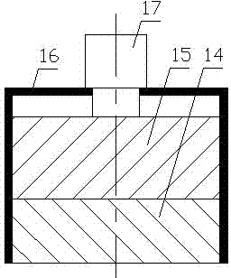
[0061] It is basically the same as Embodiment 1, except that the pressure device 17 is a hydraulic pressure device.

Example Embodiment

[0062] Examples 3 and 4:

[0063] They are basically the same as Embodiments 1 and 2, except that the impact wall 10: the impact wall 10 includes a uniform force plate 11, a force measurement device and an impact pier 13. The uniform force plate 11 faces the actual vehicle 3, and the force measurement device is located in the uniform force. Between the force plate 11 and the impact pier 13; the force measurement device is a force sensor array 12; the central console 1 is electrically connected to the force sensor array 12 and receives impact data.


PUM


Abstract

Disclosed is a pressure friction plate braking type real rail vehicle bump testing system. The pressure friction plate braking type real rail vehicle bump testing system comprises a central control panel, a launcher, a real vehicle and a bump wall. The real vehicle is arranged on the steel rails between the launcher and the bump wall; the side surface of the bump wall is provided with a bump speed measuring device and a high-speed photographing device. A braking device, a speed regulation braking device joint and a testing speed measuring device are configured and used during working condition testing; the braking device is of a pressure friction plate type structure and comprises wedge friction plates, a friction bottom plate, a friction cavity, a pressure unit and steel cables, wherein the pressure unit is a hydraulic, pneumatic, electromagnetic or mechanical adjustable pressure unit. During bump testing, the central control panel controls the working of the launcher, the bump speed measuring device, the high-speed photographing device, and a force measurement collecting device of the bump wall through programs, and receives and stores associated data; the powerless free sliding distance of the real vehicle is at least 0.1 time larger than the effective travel of the launcher; the testing bump speed between the real vehicle and the bump wall is not smaller than 25 kilometers per hour.

Description

technical field [0001] The invention relates to a real vehicle impact test system of a pressure friction plate braking type rail vehicle. Background technique [0002] Train collision accidents seriously threaten the safety of passengers. In order to reduce the losses caused by train collision accidents, the development of impact-resistant and energy-absorbing car bodies is an important way to reduce the losses caused by train collision accidents, and it is also an inevitable trend in the development of the world's railway passenger car body structures (including urban rail transit vehicles). In the study of the crashworthiness of rail vehicle structures, the real vehicle impact test is an irreplaceable research method that can truly reflect the impact process. The crashworthy and energy-absorbing vehicle body must be developed based on the actual vehicle crash test. [0003] Chinese patent application number is 200610046823.3, and the name is called " automobile passive s...

Claims


Application Information

Patent Timeline
IPC IPC(8): G01M17/007
Inventor 田红旗刘国伟梁习锋许平彭勇姚曙光王中钢
Owner CENT SOUTH UNIV
Why Eureka
Try Eureka