

Method, device and system for message pushing
A message push and message push technology, applied in the transmission system, electrical components, etc., can solve the problem of excessive resource consumption
- Summary
- Abstract
- Description
- Claims
- Application Information
AI Technical Summary
Problems solved by technology
Method used
Image

Examples
Embodiment 1
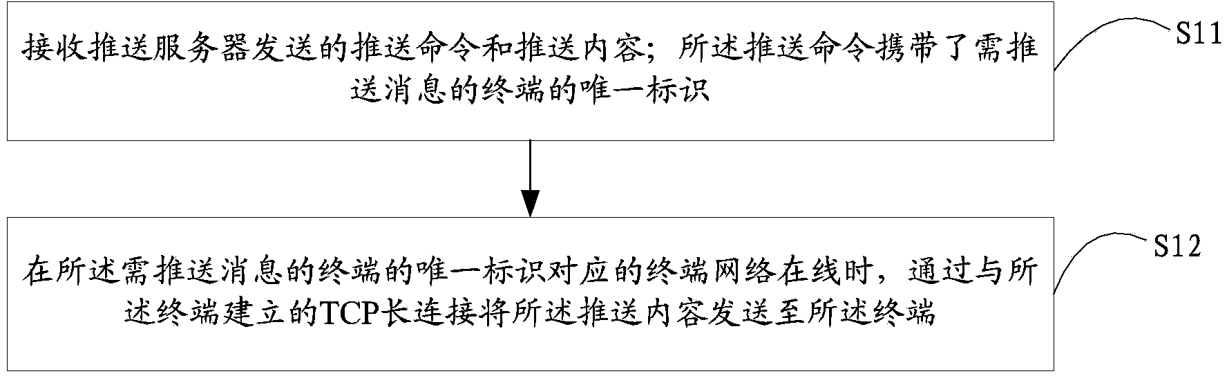
[0023] figure 1 It shows a flow chart of a message push method provided by the first embodiment of the present invention. In this embodiment, the access server receives the push content from the push server, and passes the received content through the TCP long connection established with the terminal Send to the terminal, the details are as follows:
[0024] Step S11, receiving the push command and push content sent by the push server; the push command carries the unique identifier of the terminal that needs to push the message.
[0025] In this step, the terminal that needs to push the message usually refers to the terminal that is normally connected to the network and goes online. The push server obtains the terminal access load of each main IP address and each virtual IP address configured by the access server and the unique identifier of the terminal, and according to the obtained terminal access load and terminal access load of each main IP address and each virtual IP ad...
Embodiment 2
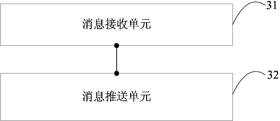
[0049] figure 2 A structural diagram of a message push device provided in the second embodiment of the present invention is shown, and for convenience of description, only parts related to the embodiment of the present invention are shown.
[0050] The message push device can be used for various information processing terminals connected to servers through wired or wireless networks, such as mobile phones, pocket computers (Pocket Personal Computer, PPC), palmtop computers, computers, notebook computers, personal digital assistants (Personal Digital Assistant) , PDA), etc., can be a software unit, a hardware unit, or a combination of software and hardware running in these information processing terminals, or can be integrated into these information processing terminals as an independent pendant or run on the applications of these information processing terminals system.
[0051] The message push device includes: a message receiving unit 31 and a message push unit 32 .
[00...
Embodiment 3
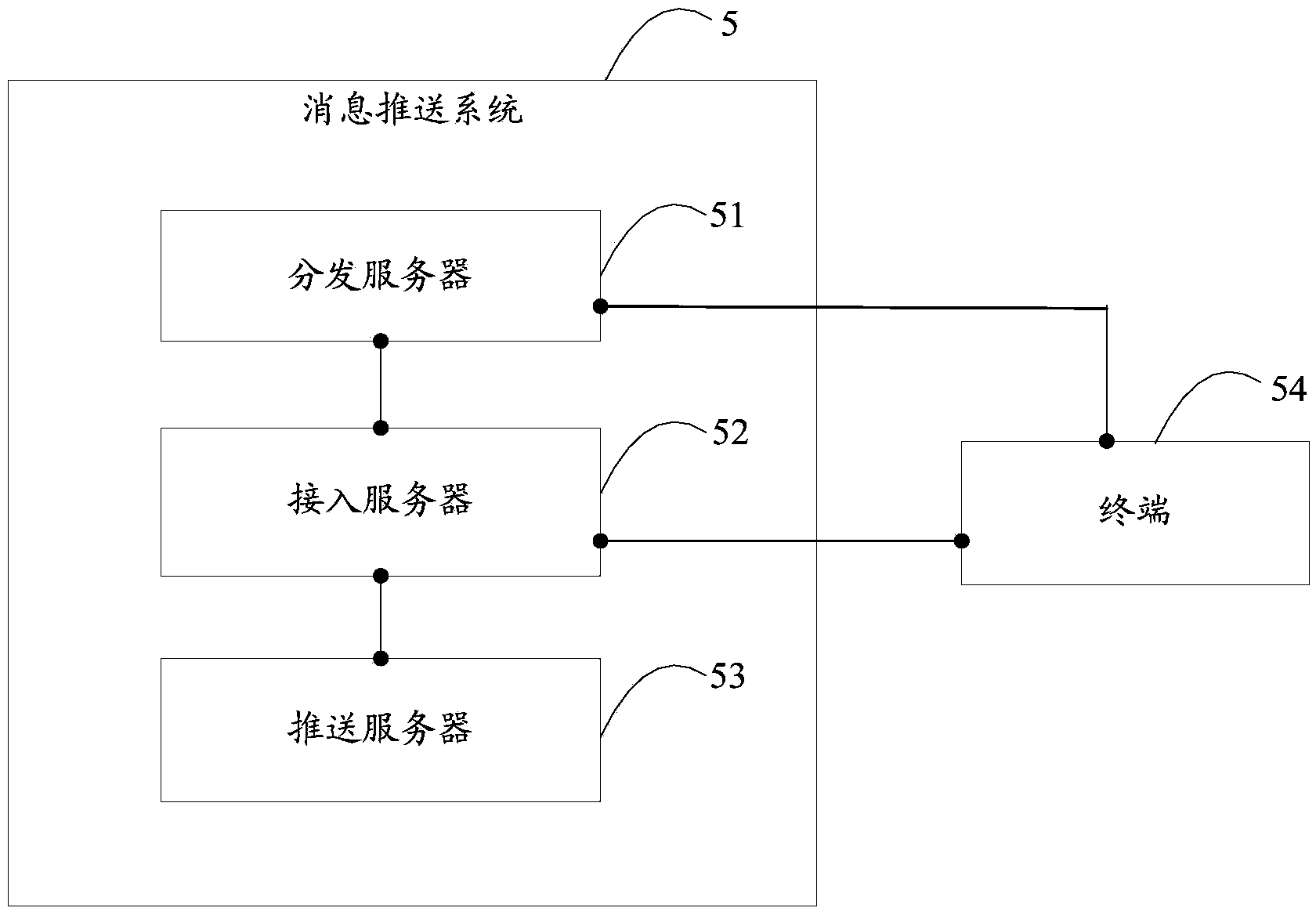
[0075] image 3 It shows a structural diagram of a message push system provided by the third embodiment of the present invention. In this embodiment, the distribution server, the access server, and the push server can be integrated on the same intelligent terminal, or can be integrated on independent on the smart terminal. For ease of description, only parts related to the embodiments of the present invention are shown.
[0076] Wherein, the message push system 5 includes a distribution server 51 , an access server 52 and a push server 53 .
[0077] The distribution server 51 is connected with the access server 52, and is used to regularly obtain the terminal access load of all IP addresses from the access server 52; the distribution server 51 is connected with the terminal 54, and is used for receiving terminal 54, send the IP address with the least access load of the terminal 54 to the terminal 54.
[0078]The access server 52 is connected to the terminal 54 and the push ...
PUM
 Abstract
Description
Claims
Application Information