A stamping device for controlling the curling and rebounding of the side wall of a stamping part
A technology for stamping devices and stamping parts, which is applied in the direction of manufacturing tools, metal processing equipment, forming tools, etc., can solve the problems of serious springback, parts scrapping, welding, assembly and other process difficulties, so as to reduce side wall curling springback, Effect of reducing stress difference and improving forming accuracy and quality
- Summary
- Abstract
- Description
- Claims
- Application Information
AI Technical Summary
Problems solved by technology
Method used
Image
Examples
Embodiment 1
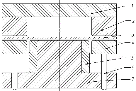
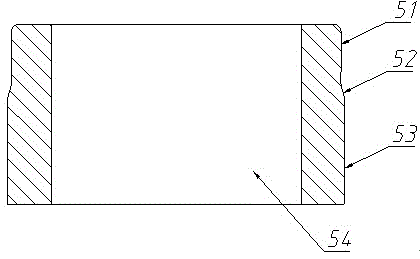
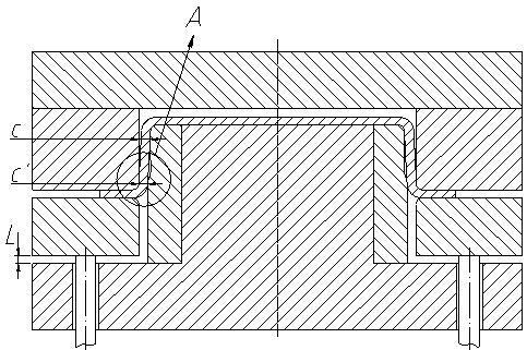
[0021] Such as figure 1 As shown, a stamping device for controlling the curling and springback of the side wall of a stamping part includes, from top to bottom, an upper die base 1, a die 2, a blank holder 4 that is driven and connected to an air ejector rod 6, and a convex ring that matches the die 2. Die 5, lower die base 7, the upper die base 1 is fixedly connected with the die 2 and moves synchronously, the punch 5 is fixedly connected with the lower die base 7, and the punch 5 includes the first stamping from top to bottom part 51 and the second stamping part 53, and the transition between the first stamping part 51 and the second stamping part 53 is smooth through the transition curve part 52, wherein the outer contour of the side wall of the first stamping part 51 is consistent with the concave die 2 The gap of the side wall is 1.2 times of the thickness of the plate to be punched, the gap between the outer contour of the side wall of the second stamping part 53 and the...
Embodiment 2
[0026] Such as figure 1 As shown, a stamping device for controlling the curling and springback of the side wall of a stamping part includes, from top to bottom, an upper die base 1, a die 2, a blank holder 4 that is driven and connected to an air ejector rod 6, and a convex ring that matches the die 2. Die 5, lower die base 7, the upper die base 1 is fixedly connected with the die 2 and moves synchronously, the punch 5 is fixedly connected with the lower die base 7, and the punch 5 includes the first stamping from top to bottom part 51 and the second stamping part 53, the transition between the first stamping part 51 and the second stamping part 53 is smooth through the transition curve part 52, wherein the outer contour of the side wall of the first stamping part 51 is consistent with the die 2 The gap of the side wall is 1.3 times of the thickness of the plate to be punched, the gap between the outer contour of the side wall of the second stamping part 53 and the side wall o...
Embodiment 3
[0031] Such as figure 1 As shown, a stamping device for controlling the curling and springback of the side wall of a stamping part includes, from top to bottom, an upper die base 1, a die 2, a blank holder 4 that is driven and connected to an air ejector rod 6, and a convex ring that matches the die 2. Die 5, lower die base 7, the upper die base 1 is fixedly connected with the die 2 and moves synchronously, the punch 5 is fixedly connected with the lower die base 7, and the punch 5 includes the first stamping from top to bottom part 51 and the second stamping part 53, the transition between the first stamping part 51 and the second stamping part 53 is smooth through the transition curve part 52, wherein the outer contour of the side wall of the first stamping part 51 is consistent with the die 2 The gap of the side wall is 1.6 times of the thickness of the plate to be punched, the gap between the outer contour of the side wall of the second stamping part 53 and the side wall o...
PUM
 Abstract
Description
Claims
Application Information
 - R&D
- Intellectual Property
- Life Sciences
- Materials
- Tech Scout
- Unparalleled Data Quality
- Higher Quality Content
- 60% Fewer Hallucinations
Browse by: Latest US Patents, China's latest patents, Technical Efficacy Thesaurus, Application Domain, Technology Topic, Popular Technical Reports.
© 2025 PatSnap. All rights reserved.Legal|Privacy policy|Modern Slavery Act Transparency Statement|Sitemap|About US| Contact US: help@patsnap.com


