Cycloid and spiral composite milling method for web with slot features

A groove feature and milling technology, which is applied in the field of mechanical parts processing, can solve the problems of affecting the processing quality of the workpiece surface, uneven force on the tool, and large cutting force of the tool, so as to improve the processing effect, avoid sudden changes in cutting force, and improve The effect of tool cutting force

Active Publication Date: 2014-07-30
NANJING UNIV OF AERONAUTICS & ASTRONAUTICS
View PDF9 Cites 26 Cited by
  • Summary
  • Abstract
  • Description
  • Claims
  • Application Information

AI Technical Summary

Problems solved by technology

[0007] The purpose of the present invention is to solve the problems of large cutting force of the tool in the processing of existing groove features, sharp points in the tool track and sudden changes in the processing direction, which cause uneven for

Method used


Image

  • Cycloid and spiral composite milling method for web with slot features
  • Cycloid and spiral composite milling method for web with slot features
  • Cycloid and spiral composite milling method for web with slot features

Examples


Embodiment Construction

[0042] The present invention will be further described below in conjunction with drawings and embodiments.

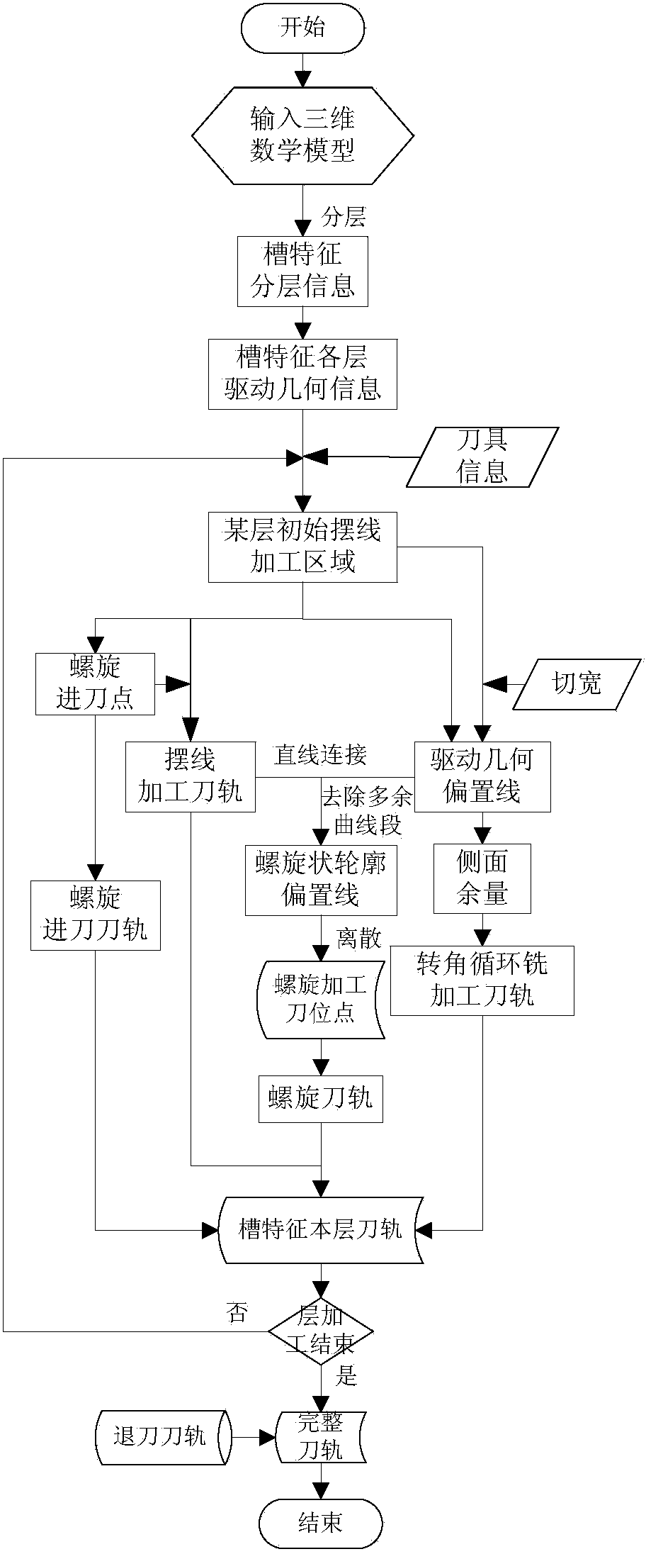
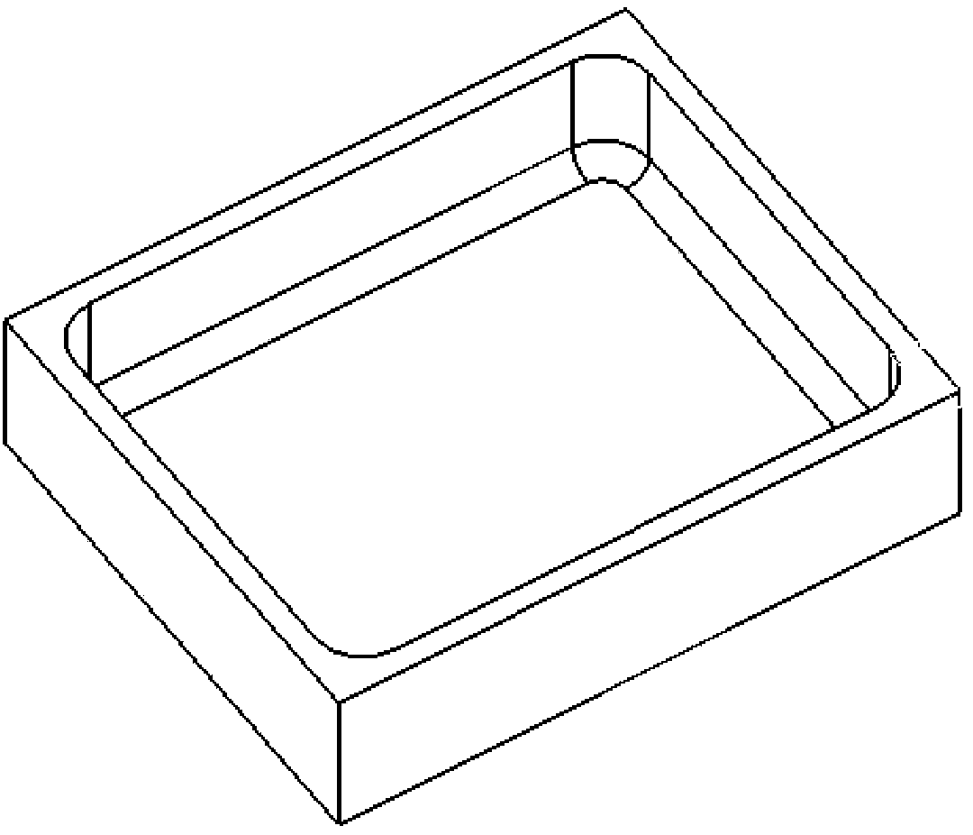
[0043] Such as Figure 1-5 shown.

[0044] A cycloidal helical compound milling method for groove-shaped structural parts. First, the groove features are layered along the tool axis to obtain the machining drive geometry of each layer, and the initial cycloidal processing area and helical entry point are calculated according to the tool information. , using spiral feed, secondly, generate cycloidal tool path in the initial cycloidal processing area; then offset the driving geometry line according to the set cutting width to obtain a series of driving geometry offset lines; offset the driving geometry The line is connected with the cycloidal tool rail, and the offset line is processed into a spiral shape to form a spiral tool rail. The cycloid is used for slotting to reduce the cutting force during the first knife. Thirdly, the spiral machining tool rail is used for pro...


PUM


Abstract

The invention discloses a cycloid and spiral composite milling method for a web with slot features. The cycloid and spiral composite milling method is characterized by comprising the following steps: firstly, feeding a tool in a spiral manner; secondly, slotting by adopting cycloid to reduce cutting force of a first tool; thirdly, machining layer by layer by adopting a spiral machining tool path and transiting by adopting variable spiral at a corner, so that the curvature changes continuously, and the cutting force mutation caused by the mutation of a sharp point and a machining direction in the tool path is avoided, the stability of a tool load is guaranteed, and the vibration of the tool is reduced; and finally, machining by adopting a corner loop milling tool path at the corner. The cycloid and spiral composite milling method can be used for machining a material which is difficult to machine; the cutting force of the first tool is reduced by cycloid slotting; the variable spiral curve is adopted at the corner of the tool path; the mutation of the sharp point and the machining direction is avoided, so that the tool path is smooth; the cutting force is reduced; the machining quality of the surface of a workpiece is improved.

Description

technical field [0001] The invention relates to a processing method of mechanical parts, especially a processing method of groove features, in particular to a CNC milling machine using spiral feeding, cycloidal slotting, spiral tool rail and corner cycle milling cutter The machining method of cycloidal helical compound milling for rail-to-groove features. Background technique [0002] Groove features widely exist in aircraft structural parts, and the current processing methods for groove features are single / two-way zigzag processing or circular cutting. This method belongs to full-cut processing during the first cut. The cutting force is large; at the same time, there are sharp points and sudden changes in the processing direction in the tool path, which cause the vibration of the tool. It affects the processing quality and precision of the surface of the part; due to the limitations of this tool path, it is not suitable for processing difficult-to-machine materials, such ...

Claims


Application Information

Patent Timeline
IPC IPC(8): B23C3/28
Inventor 李迎光郝小忠高鑫王慧洁刘长青汤立民
Owner NANJING UNIV OF AERONAUTICS & ASTRONAUTICS
Why Eureka
Try Eureka