
A Gradual Bending Tempered Glass Arc Changing Equipment

A kind of equipment and glass technology, which is applied in the field of glass bending and arc-changing equipment to achieve the effect of smooth glass bending, saving production time and uniform wind exposure

Active Publication Date: 2017-02-01
LUOYANG LANDGLASS TECH CO LTD
View PDF7 Cites 1 Cited by
  • Summary
  • Abstract
  • Description
  • Claims
  • Application Information

AI Technical Summary

Problems solved by technology

[0004] Aiming at the problems existing in the production of curved tempered glass in the prior art, especially in the production of large-sized curved tempered glass, the inventors of the present invention provide a feasible gradual shape according to the concept of pre-formed gradient bending The arc-changing equipment for curved tempered glass, the arc-changing mechanisms at both ends of the arc-changing equipment can operate independently, and can realize the arc-changing at one end of the arc-changing equipment and the straight end at the other end, so that the glass can be bent in advance at the end of the furnace, and the glass can be bent at the same time as it comes out of the furnace. Bending, no need to wait for the whole glass to be out of the furnace before bending, effectively avoiding the temperature drop when the glass is bent and deformed, resulting in glass bending crack defects. At the same time, the traditional large air grid is made into several small cooling air grids, and The cooling air grid is installed on the support beam, so that the air grid changes with the position of the support beam, ensuring that the glass is evenly winded after bending

Method used


Image

  • A Gradual Bending Tempered Glass Arc Changing Equipment
  • A Gradual Bending Tempered Glass Arc Changing Equipment
  • A Gradual Bending Tempered Glass Arc Changing Equipment

Examples


Embodiment Construction

[0026] The specific implementation manner of the present invention will be described in detail below in conjunction with the accompanying drawings.

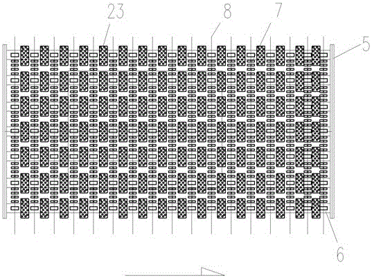
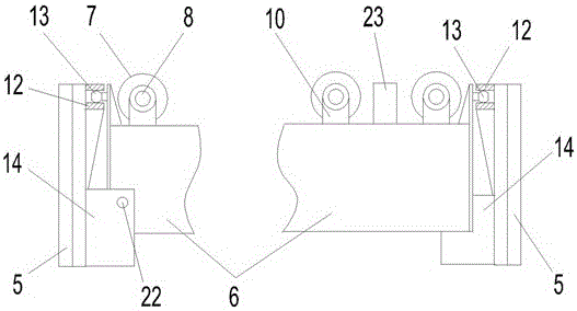
[0027] Such as figure 2 with image 3 Shown is a preferred embodiment of the curved tempered glass arc-changing device of the present invention. The direction of the arrow in the figure is the conveying direction of the glass. The arc-changing equipment includes several support beams 6 extending longitudinally and arranged at intervals in the transverse direction. A number of flexible shafts 8 and cooling air grids 23 are alternately arranged longitudinally. The supporting beam 6 serves as a cooling air duct to supply air to the cooling air grid 23 installed thereon. The two ends of the supporting beam 6 are respectively connected to the On a horizontal arc changing mechanism 5, wherein, the universal ball pair includes a universal ball 13 fixed on the support beam 6 and a card slot 12 fixed on the horizontal arc changing mech...


PUM


Abstract

The invention discloses a gradually shaped curved tempered glass arc changing device, which comprises a plurality of support beams extending longitudinally and arranged at intervals in the transverse direction. The support beams are provided with a plurality of cooling air grids at intervals in the longitudinal direction and several extending transversely and longitudinally. The flexible shafts arranged at intervals, the flexible shafts are hinged on the support beam, and a plurality of support rollers are sleeved on the flexible shaft; the two ends of the support beam are respectively connected to two transverse arc-changing mechanisms through universal ball pairs, The two transverse arc-changing mechanisms can perform arc-changing according to their respective arc-changing settings. The invention can realize that the glass can be bent as soon as it comes out of the furnace, and there is no need to wait for all the glass to be out of the furnace before starting to bend, which saves production time; when processing longer curved tempered glass, there will be no quality problems caused by the temperature difference between the end and the end of the glass during bending Defects; independent control of the horizontal variable arc unit, it can also process special-shaped glass with non-uniform curvature.

Description

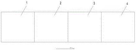
technical field [0001] The invention relates to a glass bending and arc changing equipment used in a bending tempered glass production line. Background technique [0002] Currently, if figure 1 As shown, the curved tempered glass production line mainly includes a loading table 1, a heating furnace 2, a cooling and tempering device 3 and an unloading table 4, and an air grid and an arc-changing mechanism are arranged in the cooling and tempering device 3. The traditional processing method is that the glass is loaded on the loading table 1, the heating furnace 2 heats the glass, and the heated glass is sent to the cooling and tempering device 3, and is first bent and deformed by the arc-changing mechanism, and then cooled by the air grid Tempered and cooled glass is unloaded on unloading table 4. When the glass is bent and deformed, it must wait for the glass to completely enter the cooling and tempering device before proceeding. The disadvantage of this traditional process...

Claims


Application Information

Patent Timeline
Patent Type & Authority Patents(China)
IPC IPC(8): C03B27/044C03B23/025
Inventor 赵雁张克治银勇
Owner LUOYANG LANDGLASS TECH CO LTD
Learn More