
A On-Site Diagnosis Method for Low Pressure of Safety Oil in Emergency Shutoff

A technology of critical interruption and diagnosis method, which is applied in the direction of fluid pressure actuation device, fluid pressure actuation system test, mechanical equipment, etc. problems, to achieve the effect of shortening downtime, obvious safety and economic benefits, and orderly and thorough fault finding process

Inactive Publication Date: 2016-05-11
SHANDONG ZHONGSHI YITONG GRP
View PDF5 Cites 0 Cited by
  • Summary
  • Abstract
  • Description
  • Claims
  • Application Information

AI Technical Summary

Problems solved by technology

[0002] The regulating security system and its anti-fuel oil (also known as EH oil) system of a steam turbine in a power plant are very large, including EH gas station, valve oil motor actuator, mechanical overspeed and manual blocking device, overspeed limit and emergency blocking device, online blocking Test equipment, etc., the structure and working principle of the system components and the interrelationship between the components are very complicated, resulting in a very high probability of failure of the adjustment and security system, and it is relatively difficult to troubleshoot and deal with on-site failures; once a failure occurs, often Requires downtime for processing, which can cause significant economic losses to the power plant
No matter during the commissioning of the new unit or the operation of the old unit, the adjustment and security system often has a fault of low blocking safety oil pressure. Before that, there was no set of on-site practical and relatively mature fault diagnosis methods for low blocking safety oil pressure, mainly relying on personal technology Experience adopts exploration and trial solutions, which are highly subjective and arbitrary. Various factors that cause low safety oil pressure cannot be thoroughly investigated, which makes the troubleshooting time very long and seriously affects the economic benefits of the power plant. , leaving a safety hazard for the operation of the unit

Method used


Image

  • A On-Site Diagnosis Method for Low Pressure of Safety Oil in Emergency Shutoff
  • A On-Site Diagnosis Method for Low Pressure of Safety Oil in Emergency Shutoff

Examples


Embodiment Construction

[0022] The present invention will be further described below in conjunction with the accompanying drawings and embodiments.

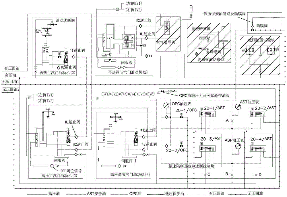
[0023] Such as figure 1 As shown, firstly, it introduces the working principle of adjusting the security system. There are two ways for the action of the security system to cause the unit to trip. One: the system is equipped with 4 AST solenoid valves, which are arranged in series and parallel. And 20-3 / AST are connected in parallel to form channel 1, solenoid valves 20-2 / AST and 20-4 / AST are connected in parallel to form channel 2, channels 1 and 2 are connected in series, and each channel has at least one AST solenoid When the valve is de-energized and opened, the channel will be in the oil draining state. Only two channels must be in the oil draining state at the same time, the oil in the AST oil circuit can be released, and the oil in the OPC oil circuit will also be released accordingly, causing all the main valves to drain. and regulating valves ...


PUM


Abstract

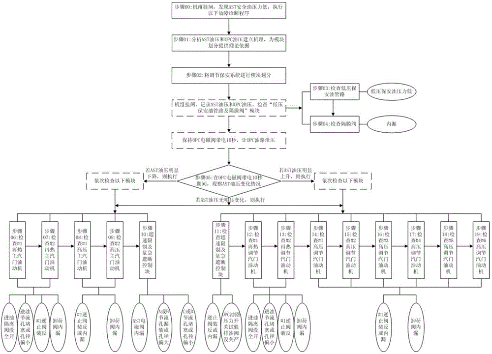
The invention discloses a spot diagnosis method for emergently interdicting low safety oil pressure. The method comprises the following steps: AST safety oil pressure and the establishing mechanism of OPC oil pressure are analyzed on the basis of the schematic diagram and the design instruction of a regulation security system to provide a basis for module division before fault diagnosis; mechanism division modules are established on the basis of the AST oil pressure and the OPC oil pressure; the numerical values of the AST oil pressure and the OPC oil pressure are recorded by a turbine latch to diagnose relative modules in sequence. According to the invention, the fault of emergently interdicting low safety oil can be diagnosed rapidly, accurately and efficiently on the spot, so that not only is the downtime of units shortened, but also various factors influencing faults can be comprehensively checked without leaving hidden danger, therefore, obvious safety benefit and economic benefit are brought to power plants.

Description

technical field [0001] The invention relates to the technical field of on-site diagnosis of faults in steam turbine regulation and security systems, in particular to a method for on-site diagnosis of low oil pressure for emergency cut-off safety oil. Background technique [0002] The regulating security system and its anti-fuel oil (also known as EH oil) system of a steam turbine in a power plant are very large, including EH oil station, valve oil motor actuator, mechanical overspeed and manual blocking device, overspeed limit and emergency blocking device, online blocking Test equipment, etc., the structure and working principle of the system components and the interrelationships between the components are very complicated, resulting in a very high probability of failure of the adjustment security system, and it is relatively difficult to troubleshoot and deal with on-site failures; once a failure occurs, often A shutdown is required for processing, which can cause signific...

Claims


Application Information

Patent Timeline
Patent Type & Authority Patents(China)
IPC IPC(8): F15B19/00
Inventor 张雷毕仲波刘浩陈志新王子奇
Owner SHANDONG ZHONGSHI YITONG GRP
Learn More