Continuously variable transmission
A continuously variable transmission, torque converter technology, applied in fluid transmission, components with teeth, belts/chains/gears, etc., can solve problems such as low efficiency, low power, and small speed change range
- Summary
- Abstract
- Description
- Claims
- Application Information
AI Technical Summary
Problems solved by technology
Method used
Image
Examples
Embodiment 1
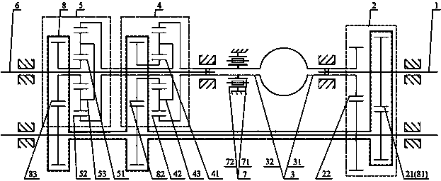
[0059] Such as figure 1 As shown in , a continuously variable transmission includes an input shaft (1), a speed-increasing unit (2), a hydraulic transmission (3), a speed-changing unit (4), a speed-combining unit (5), an output shaft (6 ), a controller (7), a speed increasing unit (2), a hydraulic transmission (3), a speed changing unit (4), and a speed converging unit are arranged between the input shaft (1) and the output shaft (6) (5), the controller (7), the speed increasing unit (2) includes an input end (21) and an output end (22), and the speed change unit (4) includes a first input end (41), a second Two input terminals (42), output terminals (43), the speed-combining unit (5) includes a first input terminal (51), a second input terminal (52), an output terminal (53), and a speed-up unit (2 ), the first input end (41) of the speed change unit (4) and the first input end (51) of the speed transfer unit (5) are respectively connected with the input shaft (1), and the sp...
Embodiment 2
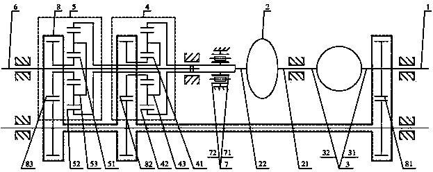
[0077] Such as figure 2 As shown in , a continuously variable transmission includes an input shaft (1), a speed-increasing unit (2), a hydraulic transmission (3), a speed-changing unit (4), a speed-combining unit (5), an output shaft (6 ), between the input shaft (1) and the output shaft (6) is provided with a speed-up unit (2), a hydraulic transmission (3), a speed-shifting unit (4), and a speed-combining unit (5). The speed increasing unit (2) includes an input end (21), an output end (22), and the speed change unit (4) includes a first input end (41), a second input end (42), an output end (43) , the speed-combining unit (5) includes a first input terminal (51), a second input terminal (52), an output terminal (53), an input terminal (21) of the speed-up unit (2), a speed-changing unit (4 ) of the first input end (41) and the first input end (51) of the converging unit (5) are respectively connected to the input shaft (1), and the output end (22) of the speed increasing u...
Embodiment 3
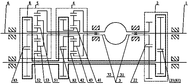
[0092] Such as image 3 As shown in , a continuously variable transmission includes an input shaft (1), a speed increasing unit (2), a hydraulic transmission (3), a speed change unit (4), a speed change unit (5), an output shaft ( 6), the controller (7), between the input shaft (1) and the output shaft (6) is provided with a speed-up unit (2), a hydraulic transmission (3), a speed-changing unit (4), a speed-combining unit (5), controller (7), the speed increasing unit (2) includes an input end (21), an output end (22), and the speed change unit (4) includes a first input end (41), The second input end (42), the output end (43), the speed transfer unit (5) includes the first input end (51), the second input end (52), the output end (53), the hydraulic transmission The input end (31) of (3), the first input end (41) of the transmission unit (4) and the first input end (51) of the speed transfer unit (5) are respectively connected with the input shaft (1), and the hydraulic tran...
PUM
 Abstract
Description
Claims
Application Information
 - R&D
- Intellectual Property
- Life Sciences
- Materials
- Tech Scout
- Unparalleled Data Quality
- Higher Quality Content
- 60% Fewer Hallucinations
Browse by: Latest US Patents, China's latest patents, Technical Efficacy Thesaurus, Application Domain, Technology Topic, Popular Technical Reports.
© 2025 PatSnap. All rights reserved.Legal|Privacy policy|Modern Slavery Act Transparency Statement|Sitemap|About US| Contact US: help@patsnap.com


