Thin and narrow groove detection device and method of strong specular reflection workpiece based on spherical light source

A spherical light source and specular reflection technology, which is used in measuring devices, optical devices, manufacturing tools, etc., can solve the problems of difficulty in accurately determining the relative position and orientation of the welding torch and the workpiece, uneven image grayscale, and limited detection accuracy. Low cost, uniform image grayscale, and high detection accuracy

Active Publication Date: 2017-04-12
TSINGHUA UNIV
View PDF7 Cites 2 Cited by
  • Summary
  • Abstract
  • Description
  • Claims
  • Application Information

AI Technical Summary

Problems solved by technology

[0005] The purpose of the present invention is to address the deficiencies of the prior art, and propose a device and method for detecting thin and narrow grooves of workpieces with strong specular reflection based on spherical light sources. In order to realize the automatic identification of the groove, especially for the automatic detection of narrow grooves with a groove gap of less than 0.1mm, problems such as uneven gray scale of the image caused by strong specular reflection on the surface, and difficulty in accurately determining the relative pose of the welding torch and the workpiece, etc.

Method used


Image

  • Thin and narrow groove detection device and method of strong specular reflection workpiece based on spherical light source
  • Thin and narrow groove detection device and method of strong specular reflection workpiece based on spherical light source
  • Thin and narrow groove detection device and method of strong specular reflection workpiece based on spherical light source

Examples


Embodiment Construction

[0039] The structure, principle and working process of the present invention will be further described below in conjunction with the accompanying drawings.

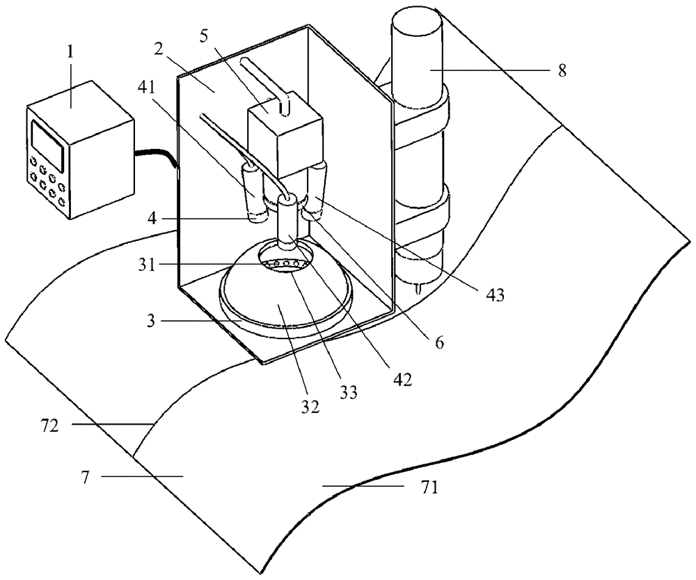
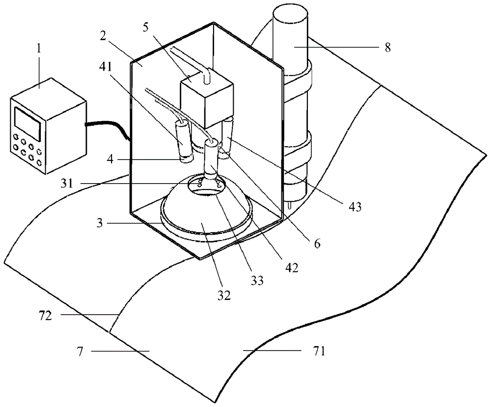
[0040] figure 1 It is a schematic diagram of the structure principle of the first embodiment of the device and method for detecting thin and narrow grooves of workpieces with strong specular reflection based on spherical light sources proposed by the present invention, including a control unit 1, a sensor housing 2, a spherical light source 3, a laser array 4, and an imaging element 5 and filter element 6. The control unit 1 is connected to the spherical light source 3, the laser array 4 and the imaging element 5 through wires; the control unit 1 sends a trigger signal to make the spherical light source 3 and the laser array 4 flash alternately, and the imaging element 5 is synchronized Collect surface images of the workpiece 7 illuminated by different light sources; the sensor housing 2 is consolidated with the welding ...


PUM

PropertyMeasurementUnit
wavelengthaaaaaaaaaa
reflectanceaaaaaaaaaa

Abstract

An apparatus and a method for detecting a narrow groove (72) of a specular reflection workpiece are provided. The apparatus includes: a spherical light source (3) configured to generate a uniform illumination on a workpiece surface (7); a laser array (4) having at least three lasers and configured to emit a laser light onto the workpiece surface (7); an imaging unit (5) configured to sample a light from the workpiece surface (7) to generate an image thereof; and a control unit (1) configured to control the spherical light source (3) and the laser array (4) to illuminate the workpiece surface (7) alternately, to control the imaging unit (5) to sample the image of the illuminated workpiece surface (7) respectively, to calculate a pose of a welding torch (8) with respect to the workpiece and a position of a center point of the groove (72) according to the image.

Description

technical field [0001] The invention belongs to the field of welding automation, and in particular relates to the design of a device and method for detecting thin and narrow grooves of workpieces with strong specular reflection based on spherical light sources. Background technique [0002] The lightweight development of aerospace components and the improvement of reliability requirements pose a major challenge to weld visual inspection and tracking. First, the groove form of the workpiece to be welded is generally I-type butt groove, the groove gap is extremely small (generally no more than 0.1mm), and a slight deviation in the relative posture of the welding torch and the groove may cause serious welding defects , has extremely high requirements for detection and tracking accuracy; second, most aerospace components are made of aluminum-magnesium alloy, with a reflectivity of more than 95%, and the strong specular reflection on the surface makes the image brightness extreme...

Claims


Application Information

Patent Timeline
Patent Type & Authority Patents(China)
IPC IPC(8): G01B11/00G01B11/03G01B11/26
CPCB23K9/0213B23K9/1274
Inventor 都东曾锦乐邹怡蓉王国庆潘际銮王力常保华
Owner TSINGHUA UNIV
Why Eureka
Try Eureka