Optical fiber laser sensor time division and wavelength division combined multiplexing method

A fiber laser and time division multiplexing technology, which is applied in the direction of using optical devices to transmit sensing components, the structure/shape of the active medium, etc., and can solve the problems of the maximum multiplexing number of only 16 array elements and a single wavelength division multiplexing technology.

Active Publication Date: 2014-07-30
NAVAL UNIV OF ENG PLA
View PDF8 Cites 12 Cited by
  • Summary
  • Abstract
  • Description
  • Claims
  • Application Information

AI Technical Summary

Problems solved by technology

According to research reports at home and abroad, the current research on fiber laser sensor array technology is limited to wavelength division multiplexing technology, and limited by the in-line pumping capability of fiber lasers and the bandwidth of the fiber laser’s outgoing light band, the use of a single wavelength Division multiplexing technology, currently the maximum multiplexing number of fiber laser hydrophone arrays is only 16 array elements, to meet the practical application requirements of large-scale arrays, it is still necessary to explore other effective multiplexing methods

Method used


Image

  • Optical fiber laser sensor time division and wavelength division combined multiplexing method

Examples


Embodiment Construction

[0019] Below in conjunction with accompanying drawing and specific embodiment the present invention is described in further detail:

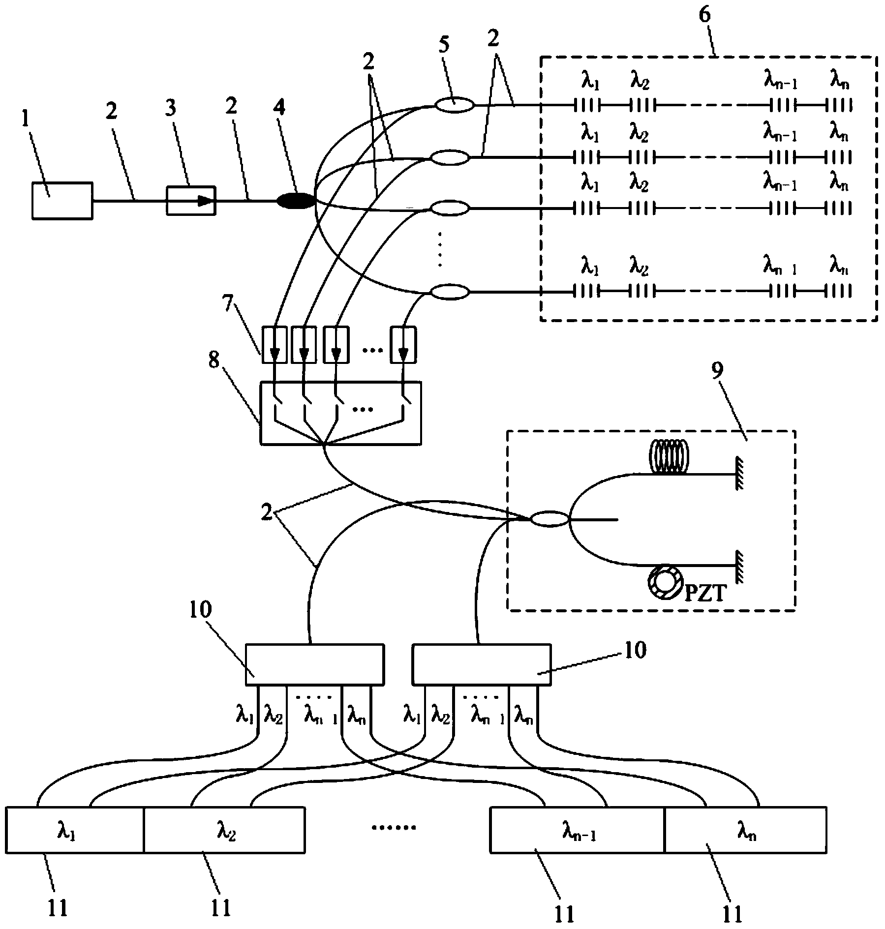
[0020] The time-division and wavelength-division joint multiplexing method of an optical fiber laser sensor comprises the following steps:

[0021] (1) Construct a time-division multiplexing structure: use an optical switch to modulate the intensity of the output light of the fiber laser in m channels to generate a narrow pulse optical signal with a high extinction ratio to achieve channel selection, use an m×1 type optical switch or use m independent optical switches, cooperate with m×1 beam combiner to realize channel selection of m channels, and then build a time division multiplexing structure;

[0022] (2) Time-division and wavelength-division joint multiplexing: use the wavelength-division multiplexing method to construct an n-element fiber laser sensor linear wavelength-division multiplexing array in each time-division multiplexing channe...


PUM


Abstract

The invention discloses an optical fiber laser sensor time division and wavelength division combined multiplexing method. The method comprises the steps that (1) intensity modulation is conducted on output light of an optical fiber laser through an optical switch so as to generate a narrow-pulse optical signal with the high extinction ratio to achieve channel selection, and a time division multiplexing structure is built; (2) an optical fiber laser sensor linear wavelength division multiplexing array is built in each time division multiplexing channel so as to achieve optical fiber laser sensor time division and wavelength division combined multiplexing; (3) displacement information of each laser wavelength in the selected channel is converted into interferometer output phase changes through the same non-equilibrium fiber optic interferometer; (4) interference information with different wavelengths is separated into n signal demodulator circuits, and a sensing signal which corresponds to the time division channel, has the corresponding wavelength and is at the position of the optical fiber laser sensor is demodulated. According to the optical fiber laser sensor time division and wavelength division combined multiplexing method, the multiplexing number of the optical fiber laser sensor array is improved to the greater degree, and the whole optical fiber laser sensing system is thinner, lighter and more reliable.

Description

technical field [0001] The invention relates to a method for multiplexing an optical fiber laser sensor, in particular to a time division and wavelength division joint multiplexing method for an optical fiber laser sensor. Background technique [0002] The application of fiber lasers in sensing has the characteristics of small size, high sensitivity, and immunity to electromagnetic interference. It has been more and more widely used in the fields of underwater acoustic detection, vibration sensing, and acoustic monitoring. In some application fields, the multiplexing scale of fiber optic laser sensors is required to be high. For the spatial gain of the acoustic signal, the array scale usually reaches more than 32 yuan. The fiber laser sensor uses the fiber laser as the sensing unit, combined with the intrinsic reusability of its wavelength, multiple fiber laser sensors can be multiplexed in a single fiber, making the array system small in cable diameter and easy to carry an...

Claims


Application Information

Patent Timeline
Patent Type & Authority Applications(China)
IPC IPC(8): G01D5/26H01S3/067
Inventor 黄俊斌顾宏灿李玉李日忠
Owner NAVAL UNIV OF ENG PLA
Why Eureka
Try Eureka