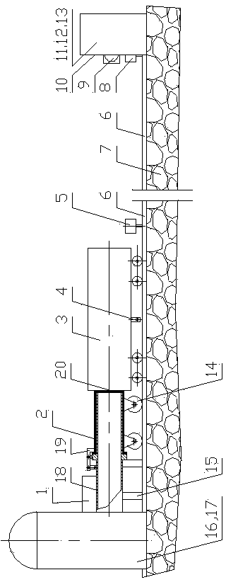
Real vehicle impact test system for pneumatic emission type railway vehicle
A test system and impact test technology, applied in railway vehicle testing, impact testing, machine/structural component testing, etc., can solve the problems of high energy level, large impact area and large volume during impact, and achieve simple and easy operation. , Construct scientific and reasonable effect
- Summary
- Abstract
- Description
- Claims
- Application Information
AI Technical Summary
Problems solved by technology
Method used
Image
Examples
Embodiment 1
[0050] A steel rail 6 is arranged on the foundation 7 between the launcher 2 and the impact wall 10; the real vehicle 3 is placed on the steel rail 6, and the launcher 2 is installed at the end of the real vehicle 3 facing away from the impact wall 10; the launcher 2 is a pneumatic launching device, It includes a walking trolley 14, a bracket 15, an air storage tank 16, an air compressor 17, a hollow piston 18, a trigger mechanism 19 and a cylinder liner 20; the middle of the hollow piston 18 is installed on the bracket 16; one end of the hollow piston 18 is connected to the air storage tank 16 is connected, the air storage tank 16 is connected with the air compressor 17; the other end of the hollow piston 18 is covered with a cylinder liner 20, the cylinder liner 20 is installed on the traveling trolley 14, and the traveling trolley 14 is placed on the rail 6; the hollow piston 18 is connected to the cylinder A trigger mechanism 19 is arranged between the sleeves 20; the trigg...
Embodiment 2
[0053] Basically the same as Embodiment 1, the difference is the impact wall 10. The impact wall 10 includes a uniform force plate 11, a force measurement acquisition device and an impact pier 13, the uniform force plate 11 faces the actual vehicle 3, and the force measurement acquisition device is located between the uniform force plate 11 and the impact pier 13; the force measurement acquisition device is: A load cell array 12; the central console 1 is electrically connected to the load cell array 12 and receives impact data.
Embodiment 3、4
[0055] On the basis of Embodiments 1 and 2, respectively, the test system is configured to use a braking device, a speed-regulating braking device joint 4 and a debugging speed measuring device 5 during debugging conditions; the speed-regulating braking device joint 4 is fixed on the actual vehicle. 3; the debugging speed measuring device 5 is arranged on one side or both sides of the steel rail 6 and is electrically connected to the central console 1, and the debugging speed measuring device 5 is located at the position when the real vehicle 3 starts to slide freely.
PUM
 Abstract
Description
Claims
Application Information
 - R&D
- Intellectual Property
- Life Sciences
- Materials
- Tech Scout
- Unparalleled Data Quality
- Higher Quality Content
- 60% Fewer Hallucinations
Browse by: Latest US Patents, China's latest patents, Technical Efficacy Thesaurus, Application Domain, Technology Topic, Popular Technical Reports.
© 2025 PatSnap. All rights reserved.Legal|Privacy policy|Modern Slavery Act Transparency Statement|Sitemap|About US| Contact US: help@patsnap.com


