Direct-current transmission line protection configuration setting method with electromagnetic coupling relationship taken into consideration

A technology for DC transmission lines and protection configuration, applied in emergency protection circuit devices, electrical components, etc., can solve problems such as fault effects, achieve effective action, solve protection malfunction, and strong engineering usability.

Active Publication Date: 2014-07-30
EXAMING & EXPERIMENTAL CENT OF ULTRAHIGH VOLTAGE POWER TRANSMISSION COMPANY CHINA SOUTHEN POWER GRID +1
View PDF5 Cites 7 Cited by
  • Summary
  • Abstract
  • Description
  • Claims
  • Application Information

AI Technical Summary

Problems solved by technology

[0006] In view of the defects of the above-mentioned prior art, the present invention proposes a DC transmission line protection configuration setting method considering the electromagnetic coupling relationship, which

Method used


Image

  • Direct-current transmission line protection configuration setting method with electromagnetic coupling relationship taken into consideration
  • Direct-current transmission line protection configuration setting method with electromagnetic coupling relationship taken into consideration
  • Direct-current transmission line protection configuration setting method with electromagnetic coupling relationship taken into consideration

Examples


Embodiment

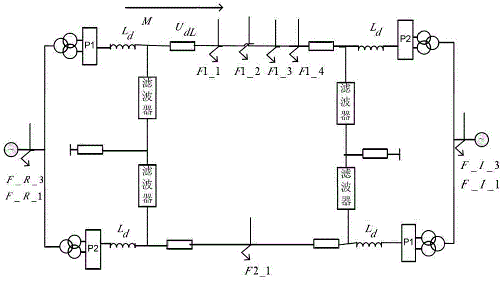
[0033] Such as figure 1 As shown, based on the engineering operation experience, the possible faults in the HVDC transmission system include: line side faults F1 and F2; rectification side bus or converter station fault F_R; converter side bus or converter station fault F_I. When considering the faults of the entire DC system, the line faults considered need to be distinguished according to the line side and the distance on the line, and the line faults are divided into F1_1, F1_2, and F1_2 according to the distance from the rectifier side of 0%; F1_3, F1_4. According to the polarity of the line fault, it is divided into F1 and F2. After a fault occurs, traveling waves and transient overvoltages often appear on the line. The capacitive effect between the high-voltage DC lines will cause electromagnetic coupling between the lines, and the voltage waveform that changes sharply on the fault side will pass through The electromagnetic coupling relationship produces a correspondin...


PUM


Abstract

The invention discloses a direct-current transmission line protection configuration setting method with the electromagnetic coupling relationship taken into consideration. The method comprises the step one of line fault analysis and judgment, the step two of protection starting, the step three of pole logic selection, the step four of disturbance elimination and the step five of boundary determination. According to the method, the situation of possible occurrence of faults of a high-voltage direct-current transmission line is objectively and accurately taken into consideration, influence on normal poles from the faulty poles due to the electromagnetic coupling relationship among polar lines is also taken into consideration, the problem that existing protection is not comprehensive enough is solved, the logic is adjusted without replacing hardware of original line protection, the engineering availability is high, the disturbance-resisting capacity of high-voltage direct-current transmission line protection to false operation possibly occurring due to the electromagnetic coupling relationship is improved, the sensitivity and the effectiveness to the line faults are enhanced, and the unification of the technicality and the economy and the unification of the reliability and the sensitivity of high-voltage direct-current transmission line protection engineering are achieved.

Description

technical field [0001] The invention belongs to the field of electric power system transmission, and in particular relates to a DC transmission line protection configuration setting method considering electromagnetic coupling relationship. Background technique [0002] With the development of my country's electric power industry, the application of high-voltage direct current transmission technology in long-distance power transmission projects is becoming more and more extensive. According to statistics, as of 2006, about 98 direct current transmission projects have been put into operation around the world. China's high-voltage direct current transmission technology only started in the 1980s, but it has developed rapidly. At present, there are 5 HVDC projects under construction in my country, as shown in Table 1-1. From 1987 when the Zhoushan DC transmission project was put into operation until August 2010, there are 15 DC transmission projects that have been completed and...

Claims


Application Information

Patent Timeline
IPC IPC(8): H02H7/26
Inventor 周全邬乾晋王海军樊友平别睿涂莉
Owner EXAMING & EXPERIMENTAL CENT OF ULTRAHIGH VOLTAGE POWER TRANSMISSION COMPANY CHINA SOUTHEN POWER GRID
Why Eureka
Try Eureka