Brake cylinder device and disk brake device

A brake cylinder and braking force technology, which is applied to brakes with brake parts, brakes with pressure braking surfaces, brakes, etc., can solve the problem of enlarged diameter, inability to increase the output of the transmission device, and large-scale devices And other issues

Active Publication Date: 2014-07-30
NABLESCO CORP
View PDF10 Cites 18 Cited by
  • Summary
  • Abstract
  • Description
  • Claims
  • Application Information

AI Technical Summary

Problems solved by technology

However, when operating the service cylinder as an active service brake operated with a pressure medium, it is not possible to increase the output by means of a transmission
Therefore, in order to increase the braking force when the normal brake cylinder operates, there is a problem of increasing the size of the device similarly to the disc brake device or the brake cylinder device disclosed in Patent Document 1 or Patent Document 2.
In addition, in the brake cylinder device disclosed in Patent Document 3, in the cylinder of the spring storage type brake cylinder, a plurality of storage springs and a plurality of transmission devices are arranged in a manner arranged along the circumferential direction of the cylinder, therefore, There is also a problem that the diameter of the cylinder main body is increased, resulting in an increase in the size of the entire brake cylinder device.

Method used


Image

  • Brake cylinder device and disk brake device
  • Brake cylinder device and disk brake device
  • Brake cylinder device and disk brake device

Examples


no. 1 Embodiment approach

[0078] disc brake

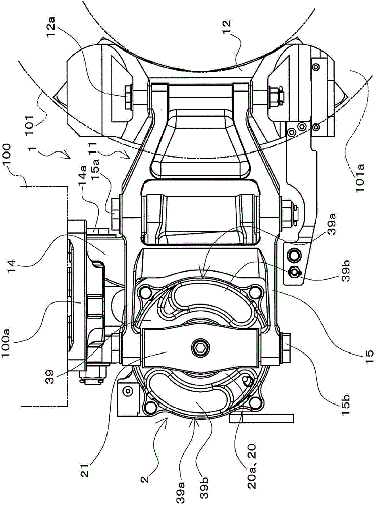
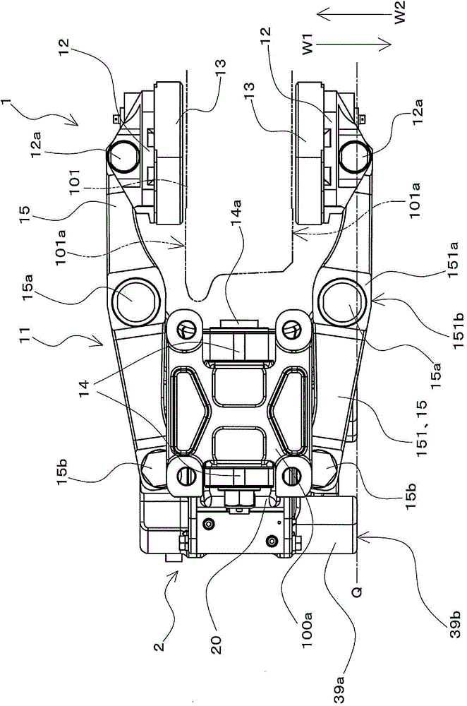
[0079] figure 1 It is a side view of the disc brake device 1 according to the first embodiment of the present invention viewed from the axle direction. in addition, figure 2 is viewed from above figure 1 A plan view of the disc brake device 1 shown. figure 1 and figure 2 The shown disc brake device 1 is configured to include the following members, etc.: a brake cylinder device 2 ; Installation; a pair of back plates (12, 12) as brake shoe holding parts for respectively holding a pair of brake pads (13, 13) as brake shoes.

[0080] A pair of brake pads ( 13 , 13 ) are attached to the caliper main body 11 via a back plate 12 . Furthermore, the disc brake device 1 is configured such that a pair of brake pads (13, 13) pinches a disc-shaped brake disc 101 when the brake cylinder device 2 operates to generate a braking force. The disk 101 is a disk on the axle side that rotates as wheels (not shown) of the railway vehicle rotate. In addition, the brak...

no. 2 Embodiment approach

[0182] Next, a second embodiment of the present invention will be described. Figure 16 It is a perspective view of a brake cylinder device 3 according to a second embodiment of the present invention, and is a diagram showing an internal structure in a cutaway section. A disc brake device according to a second embodiment of the present invention includes Figure 16 brake cylinder unit 3 shown, and with figure 1 and figure 2 The disc brake device 1 of the first embodiment shown is configured in the same manner. That is, the disc brake device of the second embodiment is configured to include the brake cylinder device 3 , the caliper main body 11 , a pair of back plates ( 12 , 12 ), and the like.

[0183] In addition, in the following description of the second embodiment, the elements having the same configuration as those of the first embodiment are denoted by or referred to by the same reference numerals in the drawings, and description thereof will be omitted. Hereinafter...


PUM


Abstract

Provided is a compact brake cylinder device capable of increasing the brake force output from a brake output unit that moves along with a rod, without requiring the device to be made larger. A piston (24) sections off a pressure chamber (43) within a main cylinder (20a), surrounds the axial periphery of a rod (22), and moves in a direct line parallel with the direction of motion of the rod (22). With the supply of a pressure fluid to the pressure chamber (43) the piston (24) moves outward relative to the main cylinder (20a) in opposition to the biasing force of a rod-biasing spring (23). An oscillating member (46) of a force-multiplying mechanism (25) is biased by the piston (24) moving in the outward direction, oscillates, and biases the rod (22), causing the rod (22) to move in the forward direction. In this way, the force-multiplying mechanism (25) multiplies the drive force from the piston (24) so as to act on the rod (22). The brake output unit (21) moves in the forward direction along with the rod (22) and outputs brake force.

Description

technical field [0001] The present invention relates to a brake cylinder device that moves a rod and outputs a braking force from a brake output portion that moves together with the rod by operating with pressure fluid, and relates to a disc brake device having the brake cylinder device. Background technique [0002] Conventionally, as a disc brake device for a railway vehicle having a brake cylinder device, a disc brake device for a railway vehicle having a brake cylinder device disclosed in Patent Document 1 is known. The disc brake device disclosed in Patent Document 1 is configured to protrude a rod in a brake cylinder device using air pressure. In addition, in this disc brake device, a pair of brake rods of the caliper body installed in such a manner that it can be relatively displaced relative to the vehicle in the axle direction are respectively connected at one end side to the rod side of the brake cylinder device and to the side constituting the cylinder body. The ...

Claims


Application Information

Patent Timeline
Patent Type & Authority Applications(China)
IPC IPC(8): F16D55/2255F16D65/14F16D65/18F16D65/56B61H5/00B61H15/00
CPCB61H5/00F16D65/18F16D65/56B61H1/00F16D55/2245B61H15/0028F16D2121/04F16D2125/64B60T13/22F16D2121/10F16D2121/14F16D2121/06B61H15/00F16D55/2255F16D65/14B60T13/588F16D55/22
Inventor 矢野正隆大野智也
Owner NABLESCO CORP
Why Eureka
Try Eureka