Modified structure of laser marking machine and method for machining hollowed-out matrix through laser marking machine

A laser marking machine and typeface technology, which is applied in the field of laser marking machines, can solve the problems of thick laser beam diameter, use of hollowing equipment, substandard fonts, etc., and achieve the goals of reducing beam diameter, increasing the speed of technicians, and increasing laser power density Effect

Inactive Publication Date: 2014-08-06
GUIYANG ZHIYUAN MACHINERY PROD DEV CO LTD
View PDF0 Cites 0 Cited by
  • Summary
  • Abstract
  • Description
  • Claims
  • Application Information

AI Technical Summary

Problems solved by technology

Since the traditional laser marking machine uses a semiconductor laser, its power is small, and the laser beam cannot penetrate the font; therefore, it can only be used as a surface marking, not as a hollowing out device.
[0003] Font is a kind of hollow thin template suitable for spraying or printing graphic marks on workpieces or equipment, usually made by hand engraving; not only the font is not standardized, but also the efficiency is low
For this reason, there are also methods of milling or wire cutting. Although some improvements have been made, when the thickness of the template is less than 1mm, the phenomenon of knife springing will occur; and due to the limitations of the size of the tool and processing equipment, it is difficult to meet the requirements of small fonts or complex fonts. pattern requirements
Although the laser cutting machine can greatly improve the efficiency and meet the requirements of some complex patterns, the diameter of the laser beam is relatively thick (0.8-2mm), which still cannot meet the special requirements of some small fonts and complex patterns.

Method used


Image

  • Modified structure of laser marking machine and method for machining hollowed-out matrix through laser marking machine
  • Modified structure of laser marking machine and method for machining hollowed-out matrix through laser marking machine

Examples


Embodiment Construction

[0015] The present invention will be further described below in conjunction with accompanying drawing and specific embodiment:

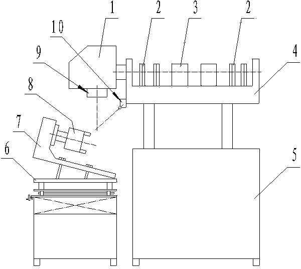
[0016] like figure 1 As shown: the laser marking machine provided by the present invention consists of a bracket 4 fixed on the cabinet 5, a fiber laser 3 fixed on the bracket, a plurality of two-dimensional lens adjustment frames 2 fixed on the bracket, and a plurality of two-dimensional lens adjustment frames 2 fixed on the bracket. The red light indicator 10 on the top and the high-speed scanning galvanometer 1, the lens 9 fixed on the high-speed scanning galvanometer, and the rotary chuck 8 fixed on the three-dimensional worktable 6 through the inclined working plate 7 are composed.

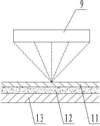
[0017] The specific method of utilizing the laser marking machine of the present invention to process hollow fonts is as follows:

[0018] 1) Fix the font 11 (that is, the workpiece) on the inclined working plate 7 through the clamp (not shown in the figure) or the...


PUM


Abstract

The invention discloses a modified structure of a laser marking machine and a method for machining a hollowed-out matrix through the laser marking machine. The laser marking machine can carry out both marking and hollowed-out machining. The invention further provides the method for machining the hollowed-out matrix. The laser marking machine is composed of a supporting frame (4) fixed on a machine cabinet (5), an optical fiber laser device (3) fixed to the supporting frame, a plurality of two-dimensional lens adjustment frames (2), a red light indicator (10), a high-speed scanning galvanometer (1), and a revolving clamping head (8) fixed to a three-dimensional worktable (6) through an inclined surface work plate (7). The method comprises the steps of workpiece positioning, focusing and scanning photoetching. Particularly, the matrix is fixed to the inclined surface work plate (7); the focal distance is adjusted, and it is ensured that the light beam of the red light indicator (10) and the light beam of the high-speed scanning galvanometer (1) coincide on the surface of the matrix; scanning photoetching is carried out on the matrix repeatedly until the light beams penetrate through the matrix.

Description

technical field [0001] The present invention relates to a laser marking machine, in particular to an improved structure of the laser marking machine; the present invention also relates to a method for processing hollow fonts by using the improved laser marking machine. Background technique [0002] As we all know, a laser marking machine is a special equipment that uses a high-energy laser beam to etch graphics, numbers, scales, etc. on the surface of an object; The lens adjustment bracket, the red light indicator, and the scanning vibrating mirror are composed of a rotary chuck fixed on the three-dimensional worktable through the inclined working plate. Since the traditional laser marking machine uses a semiconductor laser, its power is small, and the laser beam cannot penetrate the font; therefore, it can only be used as a surface marking, not as a hollowing out device. [0003] Font is a kind of hollow thin template suitable for spraying or printing graphic marks on work...

Claims


Application Information

Patent Timeline
IPC IPC(8): B23K26/362B23K26/08B23K26/70
CPCB41J2/442B41J2/47
Inventor 汪军梅岚柊
Owner GUIYANG ZHIYUAN MACHINERY PROD DEV CO LTD
Why Eureka
Try Eureka