A scanning laser-tig arc compound deep penetration welding method

A deep penetration welding and scanning laser technology, which is applied in laser welding equipment, welding equipment, metal processing equipment, etc., can solve the problems of reducing the melting width of the back of the weld, increasing the beam transmission distance, and undercutting the front of the weld. Reduce welding residual stress and deformation, improve penetration, and improve the effect of back fusion width

Active Publication Date: 2020-08-04
AVIC BEIJING AERONAUTICAL MFG TECH RES INST
View PDF6 Cites 0 Cited by
  • Summary
  • Abstract
  • Description
  • Claims
  • Application Information

AI Technical Summary

Problems solved by technology

[0005] In addition, in the existing laser-TIG arc hybrid welding, the defocusing amount of the laser beam is in a constant state; even if the scanning galvanometer laser is used, the scanning trajectory of the laser beam is realized on the surface of the workpiece, and the defocusing amount is basically kept in a constant state
In addition, the scanning galvanometer laser not only increases the beam transmission distance by designing the galvanometer inside the laser head, but also causes a certain loss of beam energy when the laser beam passes through the galvanometer.
[0006] In the process of high-power laser-TIG arc hybrid welding, when the laser defocus is zero, although the penetration of the laser beam is the strongest, the weld width on the back of the weld is also wide, but when the wall thickness of the welded workpiece is large, For example, when the workpiece wall thickness is 4mm ~ 8mm deep penetration welding of titanium alloy, the welding spatter is relatively large when the defocus is zero, and the undercut phenomenon on the front of the weld is also obvious.
When the above-mentioned high laser power is maintained, the laser defocus is negative and distributed in the range of -δ / 2 to -δ / 3. Although the welding process is more stable and the quality of the weld is better, the weld width on the back of the weld is slightly different. reduce

Method used


Image

  • A scanning laser-tig arc compound deep penetration welding method
  • A scanning laser-tig arc compound deep penetration welding method

Examples


Embodiment Construction

[0030] The embodiments of the present invention will be described in further detail below in conjunction with the drawings and examples. The detailed description and drawings of the following embodiments are used to exemplarily illustrate the principles of the present invention, but cannot be used to limit the scope of the present invention. That is, the present invention is not limited to the described embodiments and does not deviate from the spirit of the present invention. The following covers any modification, replacement and improvement of parts, components and connection methods.

[0031] It should be noted that the embodiments in the application and the features in the embodiments can be combined with each other if there is no conflict.

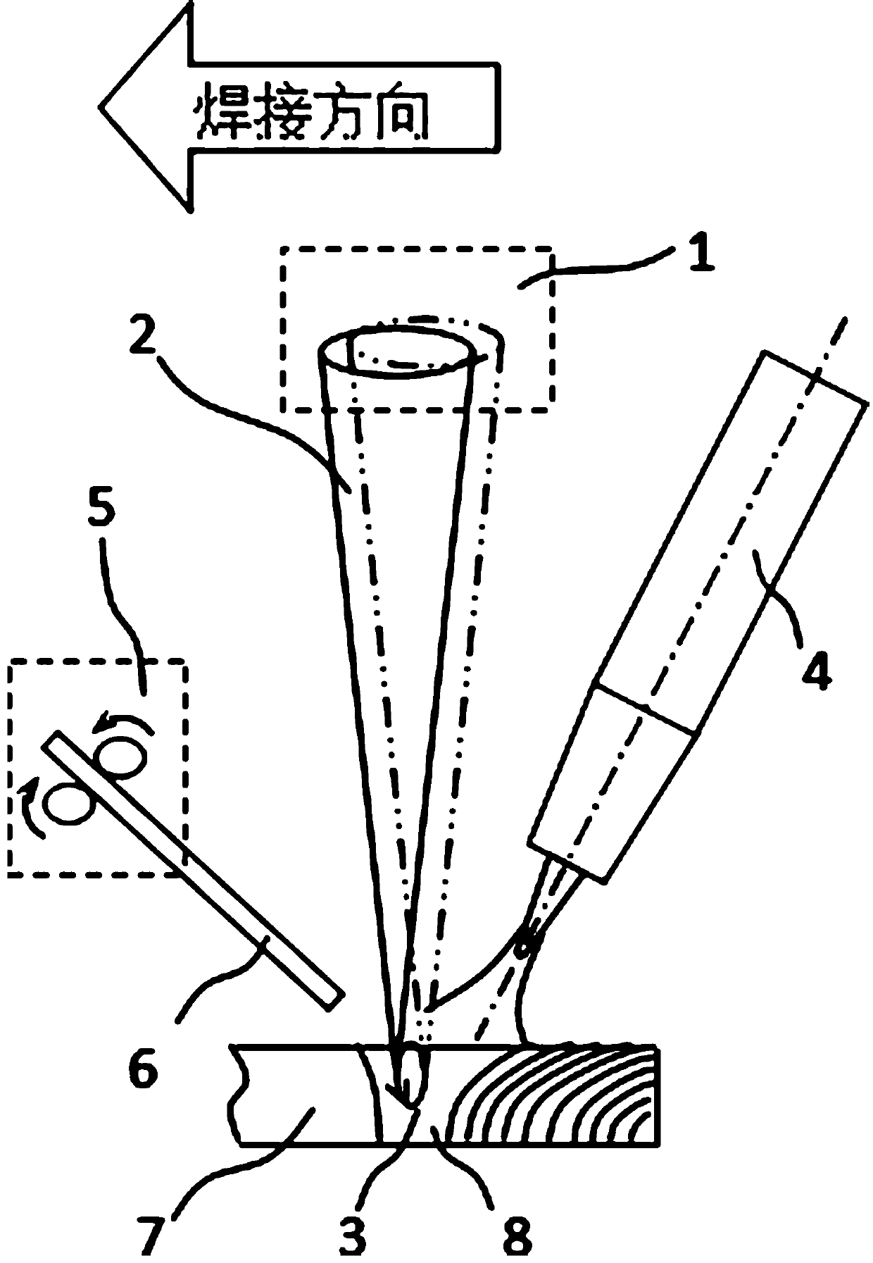
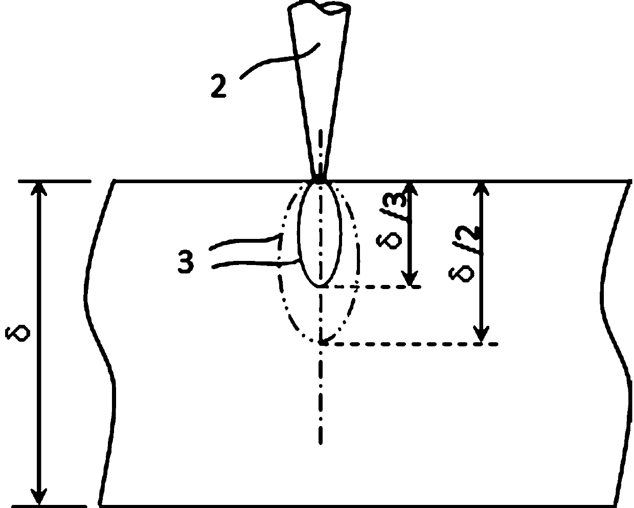
[0032] The following will refer to the attached figure 1 -Attached figure 2 The application will be described in detail in conjunction with the embodiments.

[0033] See attached figure 1 As shown, a scanning laser-TIG arc hybrid deep pen...


PUM

PropertyMeasurementUnit
diameteraaaaaaaaaa

Abstract

The invention relates to a scanning laser-TIG electric arc composite penetration fusion welding method. The method comprises the steps that a laser beam and TIG electric arc both act on a workpiece, awelding pool is formed, the laser beam is vertically downwards arranged, and the TIG electric arc is arranged on the rear side of the laser beam and is oblique by a certain angle. During composite welding, the front end of the welding pool of the workpiece is filled with a welding wire, by adjusting the scanning track, the scanning frequency and the scanning range of the laser beam, the scanningpath of a focal spot of the laser beam is oval or round in the workpiece thickness direction, a weld joint is formed, and workpiece welding is completed. By means of the method, small hole stability is facilitated, the welding quality is easily improved, then the back bead width and weld joint back width ratio of the penetration fusion weld joint is improved, and the mechanical properties of a joint are further improved.

Description

Technical field [0001] The invention relates to the technical field of welding, in particular to a scanning laser-TIG arc composite deep penetration welding method. Background technique [0002] Laser arc hybrid welding is to combine two heat sources with completely different physical properties and energy transmission mechanisms, and act on the same processing position at the same time. It can not only give full play to the respective advantages of the two heat sources, but also make up for each other's shortcomings. A new and efficient welding method. Among them, the laser-TIG arc hybrid welding process is stable (TIG welding is tungsten inert gas welding, generally called non-melting electrode gas shielded welding), the arc stability is good, and it is easy to obtain good weld formation. [0003] In the laser arc hybrid welding process, the laser heat source plays a major role in the weld penetration depth, and the arc heat source plays a major role in the weld front melt width...

Claims


Application Information

Patent Timeline
Patent Type & Authority Patents(China)
IPC IPC(8): B23K26/082B23K26/348
CPCB23K26/082B23K26/348
Inventor 许飞陈俐何恩光邢一思
Owner AVIC BEIJING AERONAUTICAL MFG TECH RES INST
Why Eureka
Try Eureka