Adjustment system for vehicle headlights

A technology for adjusting systems and headlights, applied to headlights, vehicle components, optical signals, etc., to achieve efficient transmission

Active Publication Date: 2016-05-04
ZKW GRP GMBH
View PDF6 Cites 0 Cited by
  • Summary
  • Abstract
  • Description
  • Claims
  • Application Information

AI Technical Summary

Problems solved by technology

The accompanying structural requirements for the arrangement of the adjusting element lead to a high space requirement and / or increase the processing and material expenditure of the headlight housing

Method used


Image

  • Adjustment system for vehicle headlights
  • Adjustment system for vehicle headlights
  • Adjustment system for vehicle headlights

Examples


Embodiment Construction

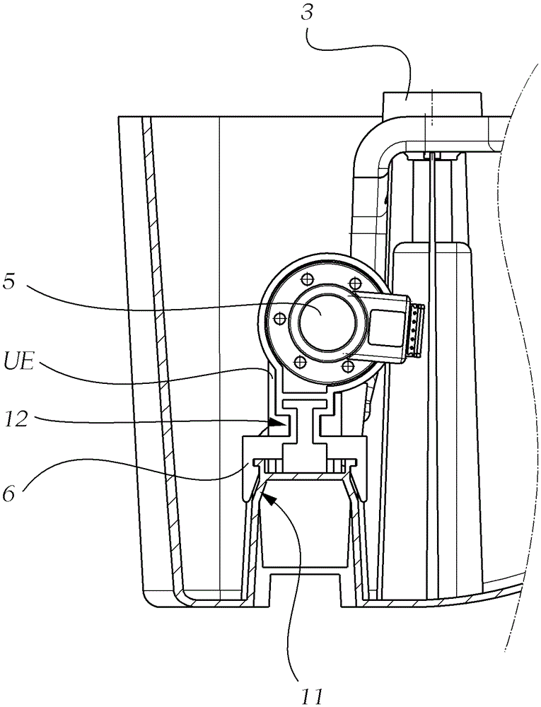
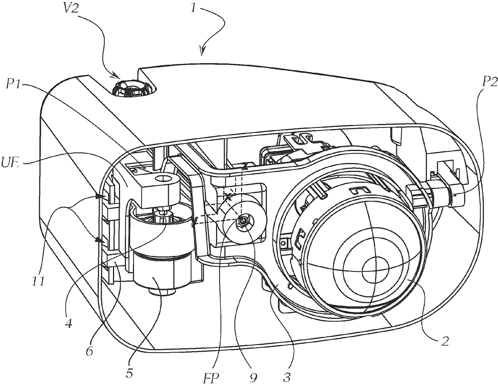
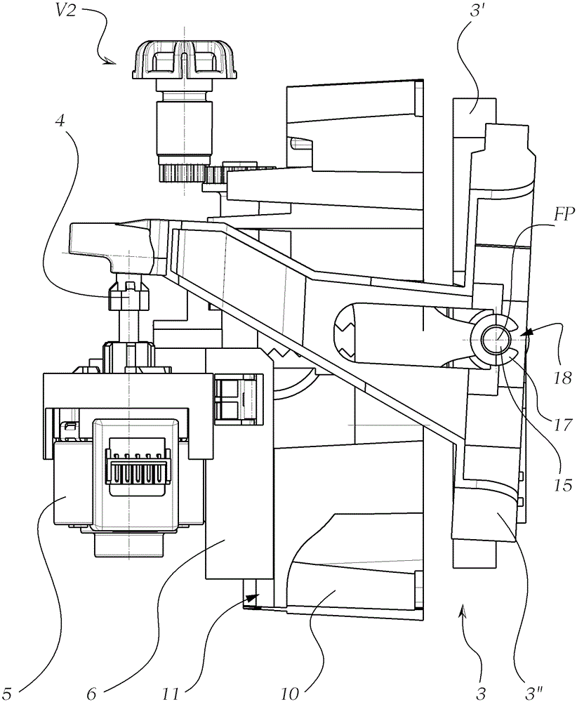
[0091] exist figure 1 A headlight housing 1 is shown in , in which a first variant of an adjustment system according to the invention for a vehicle headlight is arranged for adjusting an optically relevant component 2 . The optically relevant component 2—in the example shown is a lens, for example a projection lens of a projection module—is held here in a housing 3, wherein the housing 3 is pivotable about a first axis z and a second axis y. way to support. The first axis z is oriented vertically, so that a pivoting movement about the first axis z achieves a left-right orientation of the optically relevant component 2 . The second axis y is oriented horizontally and extends between the fixed point FP and the second adjustment bearing point P2, wherein a pivoting movement of the optically relevant component 2 about the second axis y enables an adjustment of the illumination range of the headlight, For example, dynamic lighting range adjustment is realized. The third axis x f...


PUM


Abstract

The invention relates to an adjustment system for a vehicle headlight for adjusting an optically relevant component of a vehicle headlight, in which adjustment system the optically relevant component a) can surround a first axis and a second axis (z and y) swing, wherein the first axis and the second axis are perpendicular to each other, b) the adjustment system comprises a first adjustment device, by means of which the optically relevant components can be made around the first axis ( z) swivel, wherein the first adjustment device acts on the second adjustment bearing point, and wherein c) the adjustment system comprises a second adjustment device, by means of which the optically relevant component can be swiveled about a second axis, wherein the second The adjustment device acts on the first adjustment bearing point, and wherein the fixed bearing point and the second adjustment bearing point form a second axis, wherein the triangle formed by the three bearing points is substantially horizontal in the installed state of the headlight middle.

Description

technical field [0001] The invention relates to an adjustment system for a vehicle headlight for adjusting optically relevant components of a vehicle headlight, in which adjustment system the optically relevant [0002] a) is pivotable about a first axis and a second axis, preferably a vertical axis and a horizontal axis, at a fixed bearing point, wherein the first axis and the second axis are perpendicular to each other, [0003] b) the adjustment system comprises a first adjustment device, by means of which the optically relevant component can be pivoted about a first axis, wherein the first adjustment device acts on a second adjustment bearing point, and wherein [0004] c) the adjustment system comprises a second adjustment device, by means of which the optically relevant component can be pivoted about a second axis, wherein the second adjustment device acts on the first adjustment bearing point, and wherein [0005] The fixed support point and the second adjustment suppo...

Claims


Application Information

Patent Timeline
Patent Type & Authority Patents(China)
IPC IPC(8): B60Q1/06B60Q1/068
CPCB60Q1/068B60Q1/076B60Q2200/32
Inventor C.豪尔P.巴明格
Owner ZKW GRP GMBH
Why Eureka
Try Eureka