Automatic presser foot lifting device of sewing machine

A sewing machine and presser foot lifting technology, which is applied in the field of sewing machine automatic presser foot lifting device, can solve the problems of large electromagnet driving force, easy fatigue, and large volume, and achieve low driving force requirements, high automation, and reduced manufacturing costs Effect

Active Publication Date: 2014-08-06
JACK SEWING MASCH CO LTD
View PDF5 Cites 6 Cited by
  • Summary
  • Abstract
  • Description
  • Claims
  • Application Information

AI Technical Summary

Problems solved by technology

[0004] When the presser foot lifting device of an industrial sewing machine adopts a manual device, it is often necessary to press the knee against the joystick assembly of the sewing machine to lift the presser foot when feeding materials. It is necessary to lean the knee against the joystick assembly of the sewing machine, so the labor intensity of the operator is high and it is easy to get tired
The automatic presser foot lifting device in the prior art often directly lifts the presser foot by driving the pull rod through an electromagnet, then puts the sewing material between the presser foot and the presser plate, then lowers the presser foot so that the presser foot presses the sewing material, and then proceeds Sewing, because the lifting of the presser foot is directly driven by the electromagnet driving the pull rod, so the driving force of the electromagnet is large and the volume is also large, so the configuration cost of the electromagnet is very high, which makes the manufacturing cost of the automatic presser foot lifting device very high. high
In addition, the large volume of the electromagnet also causes the volume of the industrial sewing machine to be large, which not only makes the production cost of the industrial sewing machine high, but also affects the appearance of the industrial sewing machine, and is also not conducive to the packaging and transportation of the industrial sewing machine.

Method used


Image

  • Automatic presser foot lifting device of sewing machine
  • Automatic presser foot lifting device of sewing machine
  • Automatic presser foot lifting device of sewing machine

Examples


Embodiment Construction

[0043] The implementation of the present invention will be illustrated by specific specific examples below, and those skilled in the art can easily understand other advantages and effects of the present invention from the contents disclosed in this specification.

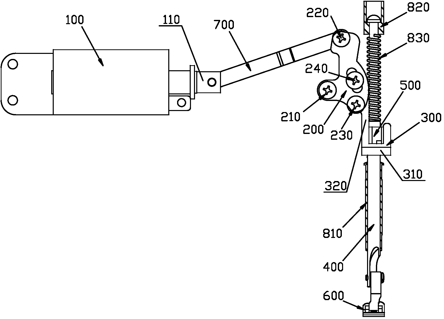
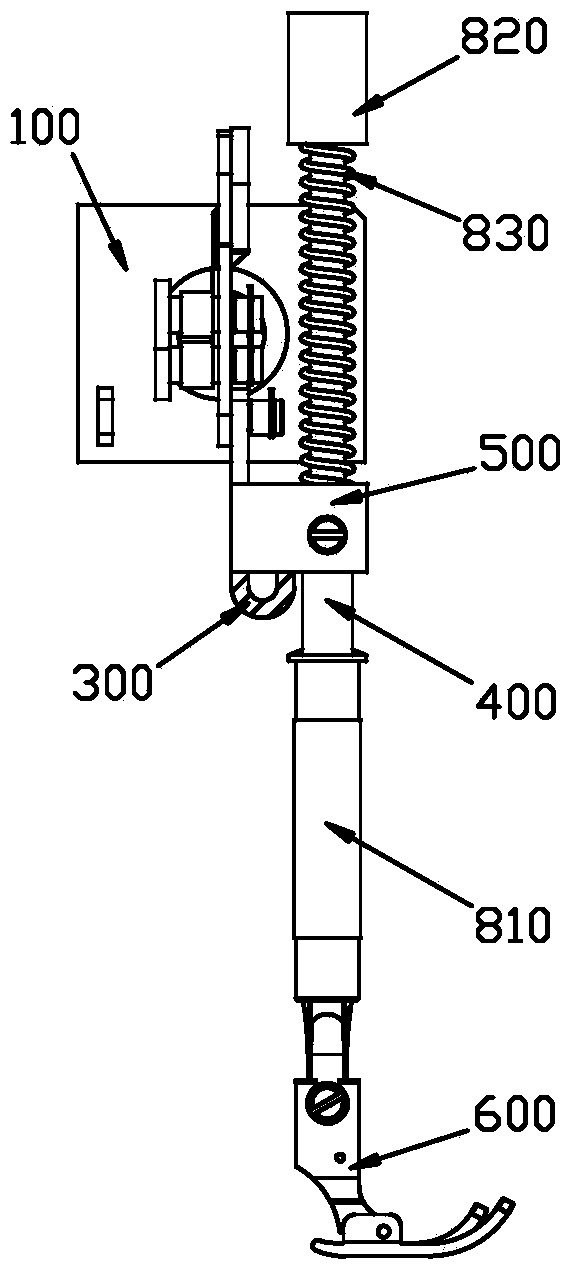
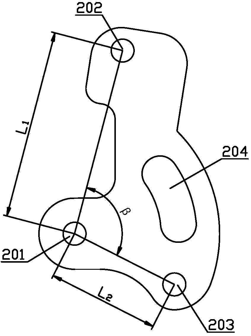
[0044] see Figure 1 to Figure 5 . It should be noted that the structures, proportions, sizes, etc. shown in the drawings attached to this specification are only used to match the content disclosed in the specification, for those who are familiar with this technology to understand and read, and are not used to limit the implementation of the present invention. Limiting conditions, so there is no technical substantive meaning, any modification of structure, change of proportional relationship or adjustment of size, without affecting the effect and purpose of the present invention, should still fall within the scope of the present invention. The disclosed technical content must be within the scope covered. At the sa...


PUM


Abstract

The invention provides an automatic presser foot lifting device of a sewing machine. The automatic presser foot lifting device of the sewing machine comprises a drive source, a transmission lever, a lifting frame, a pressing rod, a pressing rod guide frame and a presser foot. The drive source is fixed to a shell of the sewing machine. The drive source comprises a telescopic shaft. The transmission lever comprises a pivot, a long arm of force and a short arm of force, wherein the pivot is hinged to the shell of the sewing machine, and the long arm of force and the telescopic shaft of the drive source are hinged to the two ends of a connecting rod respectively. The lifting frame comprises a bottom frame and a side frame, wherein the upper end of the side frame is hinged to the short arm of force. The pressing rod guide frame and the presser foot are fixed to a pressing rod body. The portion, below the pressing rod guide frame, of the pressing rod body is matched with a first guide sleeve fixed to the shell. The upper end of the pressing rod is matched with a second guide sleeve fixed to the shell. The lower end face of the pressing rod guide frame is attached to the upper end face of the bottom frame of the lifting frame. According to the automatic presser foot lifting device of the sewing machine, automatic pressure foot lifting motion of the sewing machine can be achieved through the drive source under the action of a small drive force, so that the drive source is small in size and low in manufacturing cost, the sewing machine is more attractive, and packaging and transportation of the sewing machine are facilitated.

Description

technical field [0001] The invention relates to the technical field of sewing equipment, in particular to an automatic presser foot lifting device for a sewing machine. Background technique [0002] With the rapid development of science and technology, the degree of mechanization of clothing manufacturing is getting higher and higher. In the field of clothing manufacturing technology, there are many sewing equipment mainly industrial sewing machines, such as lockstitch sewing machines, overlock sewing machines, interlock sewing machines, etc. [0003] At present, when the industrial sewing machine is feeding, the operation of lifting and pressing the presser foot is generally performed manually or automatically through an electronic control signal, that is, the presser foot lifting device of the industrial sewing machine is a manual device or an automatic device. [0004] When the presser foot lifting device of an industrial sewing machine adopts a manual device, it is often...

Claims


Application Information

Patent Timeline
Patent Type & Authority Applications(China)
IPC IPC(8): D05B29/06D05B29/12
Inventor 卢胜龙曹仙德
Owner JACK SEWING MASCH CO LTD
Why Eureka
Try Eureka