A self-balancing elevator traction system

An elevator traction and self-balancing technology, which is applied to elevators in buildings, lifting equipment in mines, elevators, etc., to achieve the effects of reducing driving force requirements, reducing torque requirements, and reducing equipment costs

Active Publication Date: 2022-03-29
重庆市华创电梯部件有限公司
View PDF6 Cites 0 Cited by
  • Summary
  • Abstract
  • Description
  • Claims
  • Application Information

AI Technical Summary

Problems solved by technology

[0004] Secondly, although the safety level of elevators is getting higher and higher, the probability of accidents is getting smaller and smaller, but due to the different management and maintenance levels of various places, elevator accidents happen from time to time, especially the occurrence of falls, will It is of great significance to improve the protection level when elevator accidents occur due to the large loss of personnel and property

Method used


Image

  • A self-balancing elevator traction system
  • A self-balancing elevator traction system
  • A self-balancing elevator traction system

Examples


Embodiment 1

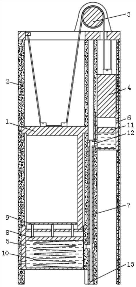
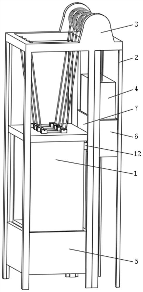
[0024] see Figure 1-2 , is only a simplified diagram of a single-section elevator. A self-balancing elevator traction system includes an elevator car 1, a guide frame 2, a traction roller 3 and a counterweight 4. Both the elevator car 1 and the counterweight 4 are connected with and The guide frame 2 is slidingly connected, the elevator car 1 and the counterweight 4 are respectively located on both sides of the traction roller 3, and the friction force of the rotation of the traction roller 3 controls the elevator car 1 and the counterweight 4 to move up and down. There is a weight-reducing water tank 5, and the lower end of the counterweight 4 is provided with a weight-increasing water tank 6, and the weight-increasing water tank 6 communicates with the weight-reducing water tank 5 through a connecting pipe 7. Flow into the weight-reducing water tank 5 or the weight-increasing water tank 6, change the weight difference on both sides of the traction roller 3, make the weight ...

Embodiment 2

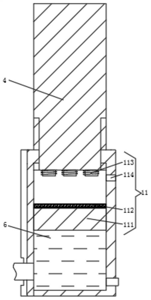
[0030] see Figure 5 , the difference from Embodiment 1 is that the communication pipe 7 is a steel pipe fixedly installed on the guide frame 2, and the connector 12 includes a fixed connection seat 121 installed on the weight-reducing water tank 5 or the weight-increasing water tank 6 and a fixed connection seat 121 installed on the communication pipe. The dynamic connecting seat 122 on the 7, each section is all correspondingly provided with the fixed connecting seat 121 corresponding to the weight-reducing water tank 5 and the weight-increasing water tank 6 respectively, and the moving connecting seat 122 is flexibly connected to the sealing sleeve 126 through the telescopic tube 123, and the sealing Sleeve 126 and fixed connecting seat 121 are provided with shut-off valve 124 with ejector rod 125 inside the connecting pipe, and the outer circumference of the connecting pipe of fixed connecting seat 121 is provided with second permanent magnet 127, and the end of sealing sle...


PUM


Abstract

The invention relates to the technical field of elevator equipment, and discloses a self-balancing elevator traction system, which includes an elevator car, a guide frame, a traction roller and a counterweight, and the elevator car and the counterweight both slide with the guide frame The elevator car and the counterweight are respectively located on both sides of the traction roller. The self-balancing elevator traction system distributes the water in the weight-reducing water tank and the weight-increasing water tank through the connecting pipe, and balances the load change in the elevator car, so that the gravity difference on both sides of the traction roller is in a small range. Reduce the driving force requirements for the rotation of the traction roller, and also reduce the torque requirements of the motor inside the traction roller, reducing equipment costs. Secondly, because the weight difference between the two sides of the traction roller is always in a small range when the elevator is running, When the elevator is out of control, the force is small, and the acceleration obtained is small, which finally reduces the falling speed of the elevator car, and when the elevator falls, the movement of the load plate can play a buffering role.

Description

technical field [0001] The invention relates to the technical field of elevator equipment, in particular to a self-balancing elevator traction system. Background technique [0002] see Image 6 , the elevator includes car, counterweight, traction system, guide system and other structures. The drive force requirement of the traction system reduces energy consumption. On the other hand, when the elevator is unbalanced, the gravity difference is small, and the destructive force when the elevator falls to the bottom or top is small, reducing personnel and property losses. [0003] Since the quality of the counterweight is fixed, and the quality of the elevator is constantly changing with the change of load or people, there is still a large quality difference between the counterweight and the car. The mass is usually the sum of the mass of the elevator car and about 50% of the rated load, that is, when the elevator is fully loaded or empty, there is a difference of about 50% of ...

Claims


Application Information

Patent Timeline
Patent Type & Authority Patents(China)
IPC IPC(8): B66B5/28B66B11/00B66B11/02B66B11/08B66B17/12
CPCB66B11/008B66B11/0226B66B5/282B66B5/284B66B17/12
Inventor 冯燕兵
Owner 重庆市华创电梯部件有限公司
Why Eureka
Try Eureka